First, use this tutorial to switch your Hummingbird into micro:bit mode.
**You must have a micro:bit and micro:bit adapter to use your Hummingbird Duo with MakeCode. Purchase it here.**
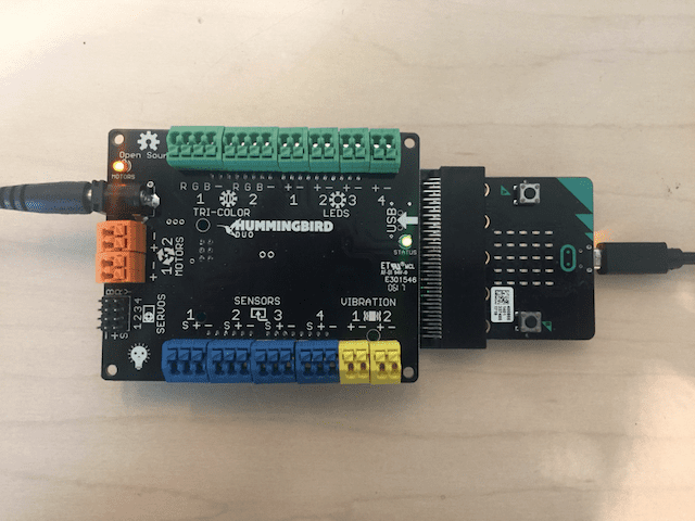
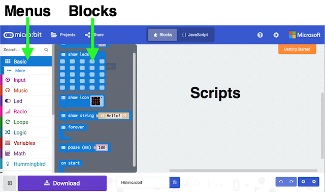
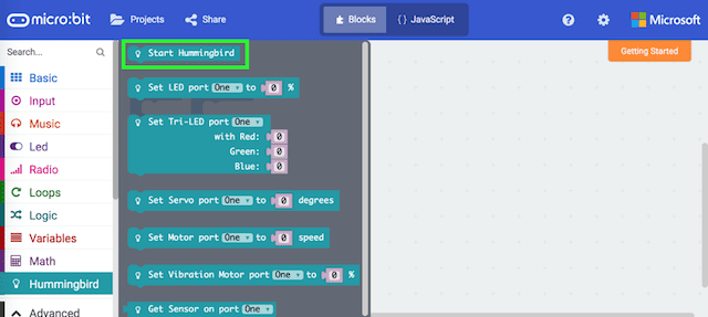
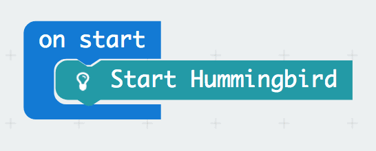
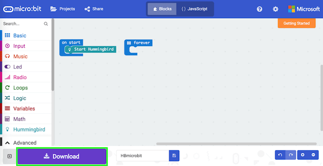
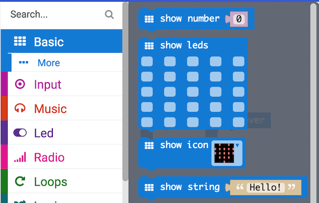
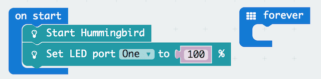
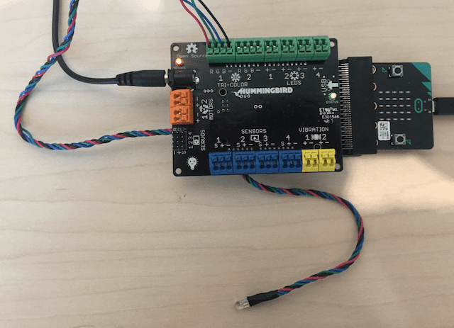
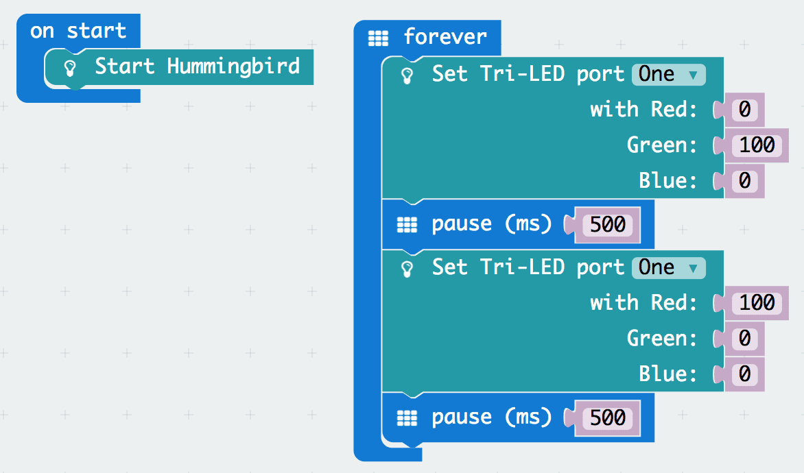
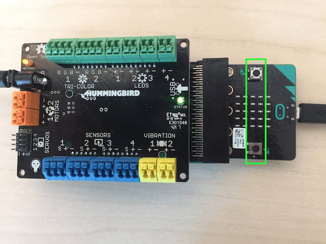
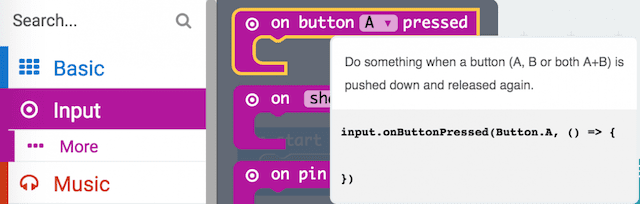
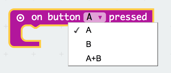
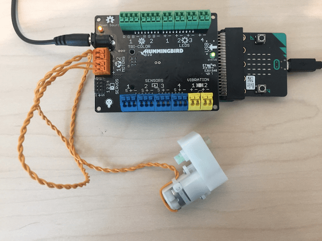
Now you can use the micro:bit to control your Hummingbird! You can write programs in the block-based MakeCode environment and then download them onto the micro:bit. Then you can disconnect the robot from the computer but keep running your program! To use the Hummingbird with micro:bit, you will need a Hummingbird micro:bit adapter. Because it is browser-based, MakeCode is compatible with Windows, Mac, Linux, and Chromebooks.
Getting Started
Using the Outputs
Use this button to open the MakeCode Environment. These lessons show the Chrome browser. We recommend Chrome, but MakeCode will work in most browsers.*
*If you would like to add Hummingbird Duo + micro:bit Adapter blocks to an existing MakeCode project, you can click on Advanced, Extensions, and copy paste this github link into the search bar (https://github.com/BirdBrainTechnologies/pxt-hummingbird-duo). Add that package, and now you have Hummingbird Duo + micro:bit Adapter blocks available in your existing MakeCode project!
micro:bit LED Array
For example, this code will display a heart on the micro:bit. Here, we have chosen to place the show icon block inside on start because we only need that block to be executed once. As long as nothing else is happening with the LEDs, all we need to do is to turn on the pattern at the beginning of the program.
Exercise 1.1
Use the show icon block to display a bunny on the micro:bit. Can you use the show leds block to make a better bunny?
Single Color LEDs
A single color Hummingbird LED can be connected to one of four ports labeled “LEDS” on the Hummingbird board. Since you have four ports, you can connect up to four single color LEDs. The black LED wire should be connected to the ‘-’ terminal, while the colored wire should be connected to the ‘+’ terminal.
Exercise 1.2
Change the brightness of the LED from 100% to 0% and upload the program again. This should make the LED turn off. Try out other numbers between 0 and 100 to explore the different levels of brightness that are possible.
Adding Delays
To blink an LED, we need the Set LED block and also a pause block, which can be found on the Basic menu. The pause block pauses the program for a certain number of milliseconds.
Once you have uploaded your program, the LED should continue to blink even when you unplug the USB cord. This is because your program is actually running on the microcontroller in the micro:bit! However, the Hummingbird and micro:bit do need power, so you will still need the power adapter or a battery pack. As long as the board has power, the program will continue to run until you upload a new program to replace it.
Exercise 1.4
Connect a second LED to your Hummingbird. Modify your program so that the second LED is off when the first is on and on when the first LED is off.
Exercise 1.5
Make the micro:bit LED display blink between two different pictures.
Tri-Color LEDs
A tri-color LED can be attached to one of the two ports labeled “TRI-COLOR” on the Hummingbird board. The four wires of the tri-color LED are red, green, blue, and black. The black wire should be connected to the ‘-’ terminal. The red wire should be connected to the ‘R’ terminal, the green to the ‘G’ terminal, and the blue to the ‘B’ terminal.
The tri-color LED actually has three tiny lights inside it. One is red, one is green, and one is blue. This is important for programming the tri-color LED with the Set Tri-LED block on the Hummingbird menu. This block requires four pieces of information, or parameters. The top drop-down menu is used to select the number of the port to which the tri-color LED is attached (One or Two). The other parameters control the amount of red, green, and blue light from 0 to 100. As an example, the block below makes a tri-color LED in port 1 blink between green and red.
Exercise 2.1
Make a tri-color LED repeat a sequence of three different colors.
Exercise 2.2
Make a tri-color LED blink on and off in your favorite color. The tri-color LED should blink two times every second. It should blink evenly – in other words, it should be off for the same amount of time that it is on.
Events
Exercise 2.3
Write a script that turns the tri-color LED on in your favorite color when the A button is pressed. When you press the B button, it should turn off.
Exercise 2.4
Use the A and B buttons to turn on different combinations of LEDs. When both buttons are pressed, all the lights should go out.
Vibration Motors
The Set Vibration Motor block is used to control the vibration motor. This block requires two parameters. The first is the port attached to the vibration motor (One or Two) and the second is the intensity of vibration from 0% to 100%. The code below will turn on the vibration motor at half the maximum intensity when the program starts.
Exercise 3.1
Write a program that repeatedly turns both a vibration motor and a single color LED on for four seconds and then off for four seconds.
Gear Motors
The gear motor can be attached to either of the ports labeled “MOTORS” on the Hummingbird board. It does not matter which wire is attached to ‘+’ and which is attached to ‘-.’
Exercise 3.2
Use a small screwdriver to attach a wheel to the motor so that you can see it move more easily (or just place the wheel on the motor without using a screw). Try several speeds between 0 and 100. Describe how the speed affects the motor. Try several negative speeds. What does it mean for the speed to be negative?
Important Note
You may notice that your motor rotates clockwise for positive numbers, while your neighbor’s rotates counterclockwise for the same number. This just means that you and your neighbor chose ‘+’ and ‘-‘ differently when you plugged in your motors. Either way is fine!
Servo Motors
A servo motor is a motor that moves to a particular angle. The Hummingbird servo motor can rotate to any angle from 0° to 180°.
The servo motor has a small plug. This plug should be connected to one of the four sets of pins in the “SERVOS” section of the Hummingbird board. Each set of three pins is one servo port. The black wire should be connected to the ‘-’ pin, the red wire to the ‘+,’ and the yellow wire to the ‘S.’
Use hot glue to attach a popsicle stick to the white plastic circle on the servo motor. This will help you to see the movement of the servo motor more easily. If you don’t want to use hot glue, you can tape a feather to the plastic circle.
Exercise 3.4
Make the servo move repeatedly through a series of four different positions. Make the tri-color LED a different color at each position.
Exercise 3.5
Use the buttons to move the servo to three different positions.
Building Tip
Before you start building with a servo, always set it to 90°. This will make sure that the servo can move both left and right once it is attached to your robot.
The for block uses a variable. A variable is just a name that represents a value. By default, the name of the variable is “index,” though you can click the drop-down menu for an option to rename it. The parameter determines the number of times that the for loop repeats the blocks inside it.
An example program using the for block is shown below. Try out this program and see your LED repeatedly increase in brightness. You can find the red index block on the Variables menu.
The for block uses the index variable to keep track of how many times the commands inside the loop have been repeated. The logic of the loop is shown in the flowchart below. When the program reaches the for block, it sets the variable index to 0 and then checks if the value of index is less than or equal to the maximum, which is 100 here. If it is, the blocks inside the for are executed, and the value of index is increased by 1. Then the program returns to the test at the top of the loop and checks again whether index is less than or equal to 100. This process continues until that test fails. When index is not less than or equal to 100, the loop ends and the program moves on to the block below the for block. In this case, the program pauses for two seconds, and then the for loop starts all over again.
Exercise 4.2
Write a script that moves the servo slowly from 0° to 180°. For an extra challenge, make the servo move slowly from 0° to 180° and then slowly back to 0° (you will need two for loops).
Exercise 4.3
Write a program to make the tri-color LED repeatedly transition from red to blue.
Exercise 4.4
Are you ready to use all the outputs? Write a program that includes the following:
- At least three LEDs
- At least two different kinds of motors
- At least one for loop
- Explore using the blocks on the Music menu to add sound! To hear the sounds, plug your earbuds into the headphone jack on the micro:bit adapter.
The LEDs and motors are output devices. Programs send commands to these devices to make something happen. The Hummingbird sensors, on the other hand, are input devices. They send information to the program. The program can use this information to control a light or a motor or to make a decision. The micro:bit also contains sensors; for example, the micro:bit accelerometer senses when you tilt the device.
All sensors use the Get Sensor block on the Hummingbird menu. This block requires only one parameter, the port of the sensor. This block has a different shape because it measures a value and passes that value back to the program. In computer science, passing a value back to the program is called returning a value. The value of the Get Sensor block is always in the range 0-100 (arbitrary units). This value represents a voltage between 0 and 5 V.
Exercise 5.1
Connect a rotary knob and a single color LED to the Hummingbird (port 1 for both), and then try out the script shown above. What happens as you turn the rotary knob back and forth?
Exercise 5.2
Use the knob to control a gear motor and the amount of red in a tri-color LED (the amount of green and blue can be whatever you want). These components should change at the same time.
Exercise 5.3
Try out the script shown above and make sure that the servo can move from 0° to 180°.
You can also use the micro:bit accelerometer to control LEDs and motors. You can measure the micro:bit’s acceleration using the acceleration block on the Input menu. The accelerometer can measure the tilt of the micro:bit in three directions, which are called x, y, and z. You can use the drop-down menu in the acceleration block to select one of these directions.
The value of the acceleration block is always between 0 and 1024. To use it to control a Hummingbird output, you need to use the division operator to reduce this value to a range within 0 to 100. For example, the script below will use the three directions of acceleration to control the three light elements of the tri-color LED.
Exercise 5.5
Try out the script shown above. How do you need to tilt the Hummingbird to change the acceleration in the x, y, and z directions?
Exercise 5.6
Use the micro:bit accelerometer to control the angle of a Hummingbird servo.
The light sensor measures the amount of light around it. Like the rotary knob, you can find its value with the Get Sensor block on the Hummingbird menu. This value will be between 0 and 100. To see the value of the light sensor, you can use the show number block from the Basic menu. This script will scroll the sensor value across the micro:bit LED array each time you press the button A.
Exercise 6.1
What is the value of the light sensor in the light of your room? What is the value when you cover the light sensor? Write down these values, you will need them later.
Exercise 6.2
Attach the light sensor to the Hummingbird board and use it to control the speed of a gear motor. What happens when you cover and uncover the light sensor? For an extra challenge, use math blocks so that the motor moves at maximum speed in the negative direction when the light sensor value is 0 and at maximum speed in the positive direction when the light sensor value is 100.
Making a Decision
The Boolean block in our sample program checks whether the value of the light sensor is less than 20. If this is true, the block inside the then section of the if then else is executed, and the LED turns on. If the Boolean block is false, the block inside the else section of the if then else is executed, and the LED turns off. The value that a Boolean block uses to make a decision is called the threshold. In the sample program, the threshold is 20. If the value of the light sensor is less than this threshold, the program decides that it is dark.
Exercise 6.3
Try out the sample program shown above. You may need to adjust the threshold based on the lighting in your room. The average of the two values you measured in Exercise 6.1 is a good starting threshold.
Exercise 6.4
Write a program that blinks a red LED and moves a servo motor when a bright light is detected. When there is no bright light, the LED should be off and the servo should not move.
Exercise 6.5
The Boolean block in the if then else is checked each time the program repeats the decision. However, the Boolean block is not checked during the statements inside the then or else parts of the block. Try out this script. In this script, the motor should move in one direction when the light sensor detects that it is dark and the other direction when it is bright. When you run this program, you will notice that the program does not respond quickly to a change in the amount of light. How can you modify this program to make it respond more quickly to a change in the value of the light sensor?
The Hummingbird distance sensor emits infrared waves. If there is an object near the sensor, infrared waves bounce off the object and return to the sensor. The angle of reflection is used to measure how far away the object is.
Exercise 7.1
Attach the distance sensor to the Hummingbird board and use it to control a single color LED. How does the brightness of the LED change as you move an object closer to the distance sensor?
Important Note
The distance sensor can detect objects roughly 8-100 cm from the sensor; it works best in the range of 20-60 cm.
Exercise 7.2
Write a script that turns on a vibration motor when an object is close to the distance sensor. Otherwise, the vibration motor should be off. What is an appropriate threshold for the distance sensor? You may need to experiment to find a good threshold.
An if then else uses a Boolean block to choose one of two possibilities. You can also use Boolean blocks in loops, such as the while do block (Loops menu) in MakeCode. The while do block uses a Boolean block to determine how many times the blocks inside it will be executed. The blocks inside the loop will be repeated as long as the Boolean block is true. When the Boolean block is false, the program will move on to whatever block is below the while loop.
For example, the loop below will blink a tri-color LED as long as nothing is close to the distance sensor. When the value of the sensor is greater than or equal to 20, the LED will stop blinking and turn green.
Exercise 7.4
Create an alarm to detect people (or cats) approaching your computer! When a someone is nearby, use lights and motors to alert you to their presence. The lights and movement should continue until you turn the knob sensor clockwise. You will need to reset the knob sensor to the counterclockwise position before using the alarm again.
Exercise 7.5
Create a simple version of whack-a-mole. Use two servos as your “moles.” Each servo will correspond to one sensor: servo 1 to the distance sensor and servo 2 to the light sensor. The program should randomly select a servo and turn it to 90° to make the mole pop up. The mole should stay up until the user triggers the corresponding sensor. For example, the light sensor servo should stay at 90° until the user covers the sensor. Then the servo should move back to 0°. After the servo returns to 0°, add a random delay of 1-3 seconds before another mole pops up. After you have this basic game working, how can you add more moles? What other features can you add?
Important Note
For this section, you will need two micro:bits.
If you have two or more micro:bits, they can communicate with each other! This means that you can create robots that interact with one another. To do this, you will use the blocks in the Radio menu.
To send radio messages to one another, two (or more) micro:bits must be set to the same radio group. In the on start block for each micro:bit, use the radio set group block to assign both micro:bits the same radio number. Here, the radio group number is 120.
A micro:bit can send a message using the radio send string block or the radio send value block. Assume that for the script below, the Hummingbird light sensor is attached to port 1. When the light sensor detects that it is dark, the micro:bit sends the string “dark.” Otherwise, it sends the string “light.”
A second micro:bit can listen for the messages sent by the first one. If the first micro:bit is using radio send string, then the second should use the on radio received receivedString to listen for messages. When it receives a string, it can check to see which of the two possible messages it has received. The script below turns on an LED when it receives the message “dark.” The LED turns off if it receives the message “bright.”
Exercise 8.2
Program one micro:bit to send a different radio message when each combination of its buttons (A, B, A+B) is pressed. Program a second micro:bit to respond to these messages. Each radio message should cause a servo connected to the second Hummingbird to move to a different angle.
Exercise 8.3
Use the accelerometer in one micro:bit to control the speeds of two gear motors attached to Hummingbird connected to a second micro:bit. You can use the code below as a starting point.
- The first micro:bit is sending two accelerometer values. Because it is sending two values, it calls them “X” and “Y” so the robot that receives them knows which is which.
- The second micro:bit should make the two motors move in the same direction when it receives an “X” value and in different directions when it receives a “Y” value. The on radio received block shown received both the name and the value sent by the first micro:bit.
- You can use your work to make a simple rover that is controlled by the first micro:bit! This tutorial may be helpful for building a rover.