
CREATE Lab Visual Programmer: Lessons for Hummingbird

Before you can build an awesome robot with your Hummingbird, you need to know how to use all the parts.

This lesson will first show you how to use the Hummingbird outputs, the lights and motors. These components are called outputs because programs in the CREATE Lab Visual Programmer send commands to them to make something happen. Then you will learn how to use the Hummingbird inputs, the sensors that provide information to the robot about its environment.

Keys Available

Keys are available to educators.

Get Access

Getting Started

Start by watching the videos shown below.

The first will show you how to attach components to the Hummingbird board, and the second will show you how to connect the Hummingbird to the computer and gives a very brief description of the CREATE Lab Visual Programmer.

Get The Comic!

Use the USB cord to connect the Hummingbird to your computer, and connect the AC power adapter.

Programming with the CREATE Lab Visual Programmer

Open the CREATE Lab Visual Programmer.

If your Hummingbird is not connected to the computer, you will see this screen.

When the Hummingbird is connected, you will see the screen shown below. This screen allows you to decide where you want to store your Hummingbird files. If you want to choose a USB drive or a particular folder, click Choose Location… and navigate to that location. Otherwise, click Use Default Location. The default location is a folder called CREATELab that is in your home directory.

After you select where to save your files, you will be ready to start programming. You will see a screen that looks like this.

Using the Outputs

Module 1: Lights

First, you will learn to use the lights, which are also called LEDs. The Hummingbird kit contains two types of LEDs, single color LEDs and tri-color LEDs. Single color LEDs have two wires, while tri-color LEDs have four wires.

A single color LED can be connected to one of four ports labeled “LEDS” on the Hummingbird board. Since you have four ports, you can connect up to four single color LEDs. The black LED wire should be connected to the ‘-’ terminal, while the colored wire should be connected to the ‘+’ terminal. Connect a single color LED to port 1 now.

A tri-color LED can be attached to one of the two ports labeled “TRI-COLOR” on the Hummingbird board. The four wires of the tri-color LED are red, green, blue, and black. The black wire should be connected to the ‘-’ terminal. The red wire should be connected to the ‘R’ terminal, the green to the ‘G’ terminal, and the blue to the ‘B’ terminal. Connect a tri-color LED to port 1 now.

To turn on your single color LED, click on port 1 under the label LEDsin the CREATE Lab Visual Programmer.

Exercise 1.1

Move the slider for LED 1 back and forth.

You should see the LED get brighter and dimmer. Set LED 1 to 0. This should turn the LED off. Then set LED 1 to 100. This is the maximum brightness of the LED.

Building Tip

LEDs are quite small, but you can use a styrofoam ball to diffuse the light. This will make the light appear larger.

The tri-color LED actually has three tiny lights inside it. One is red, one is green, and one is blue. This is important for programming the tri-color LED. To turn on your tri-color LED, click on port 1 under the label Tri-Color LEDs. You will see three sliders appear. The tri-color LED actually has three tiny light elements inside it. One is red, one is green, and one is blue. You can use the three sliders to control the amount of red, green, and blue light.

Exercise 1.2

What color combination will make the tri-color LED purple? How can you make aqua or yellow? After you have explored the different possible colors, set the tri-color LED to your favorite color.

You have created an expression to turn on the single color LED and the tri-color LED. Now save it by clicking on the Save button. Then give your expression a useful name and click OK

To turn the lights off, you will need a second expression. Click New, and then click OK when the program asks you if you are sure you want to create a new expression.

Exercise 1.3

In your new expression, click on the ports for your single color LED and your tri-color LED. Set all the sliders to 0 to turn both LEDs off. Then save this expression.

Module 2: Creating a Sequence

Now that you have two expressions, you are ready to put them together to make a sequence that blinks the two LEDs. Click on the Sequence Builder tab. You will see this screen.

Drag your two expressions into the Sequence Builder.

When you click on the Play button, then LEDs should go on, then off.

To make the LEDs blink repeatedly, click on the arrow to put your sequence in Play Loop mode. Then click Play.

Be sure to use the Save button to save your sequence!

To stop a sequence that is playing, just click the Stop button.

To make the LEDs blink faster or slower, click on the clock in each expression block. This lets you set how long the expression will last.

Exercise 2.1

Modify your sequence so that the LEDs blink on and off at least ten times in five seconds. The LEDs should blink evenly – in other words, they should be off for the same amount of time that they are on.

Exercise 2.2

Modify your program so that instead of blinking on and off, the tri-color LED blinks in two different colors. To do this, you will need to modify your expressions, not the sequence.

Exercise 2.3

Write a sequence that uses four different colors for the tri-color LED and four different intensities for the single color LED. You will need to create some new expressions!

Module 3: Motors

The Hummingbird kit works with three different kinds of motors: vibration motors, servo motors, and gear motors.

Vibration Motors

A vibration motor can be attached to one of the two ports labeled “VIBRATION” on the Hummingbird board. It does not matter which wire is attached to ‘+’ and which is attached to ‘-.’

To control the vibration motor, select the correct port under the Vib. Motors label in the CREATE Lab Visual Programmer. You can then use the slider to set the speed of vibration from 0 to 100. 0 means no vibration, and 100 means maximum vibration. In the expression below, the speed is set to 50.

Exercise 3.1

Create two expressions that use the vibration motor and a single color LED. In the first expression, both components should be on. In the second expression, both components should be off. Then use these expressions to create a sequence that repeatedly turns the vibration motor and LED on for four seconds and then off for four seconds.

Building Tip

Small, very light items such as googly eyes can be attached to a vibration motor so that they move when the motor vibrates.

Servo Motors

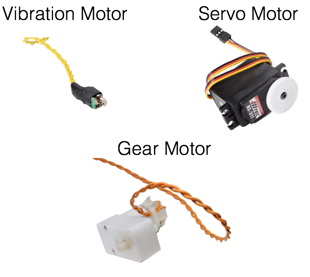
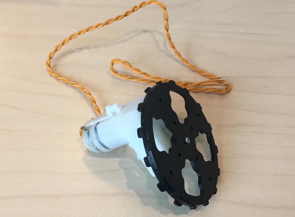
A servo motor is a motor that moves to a particular angle. The Hummingbird servo motor can rotate to any angle from 0° to 180°.

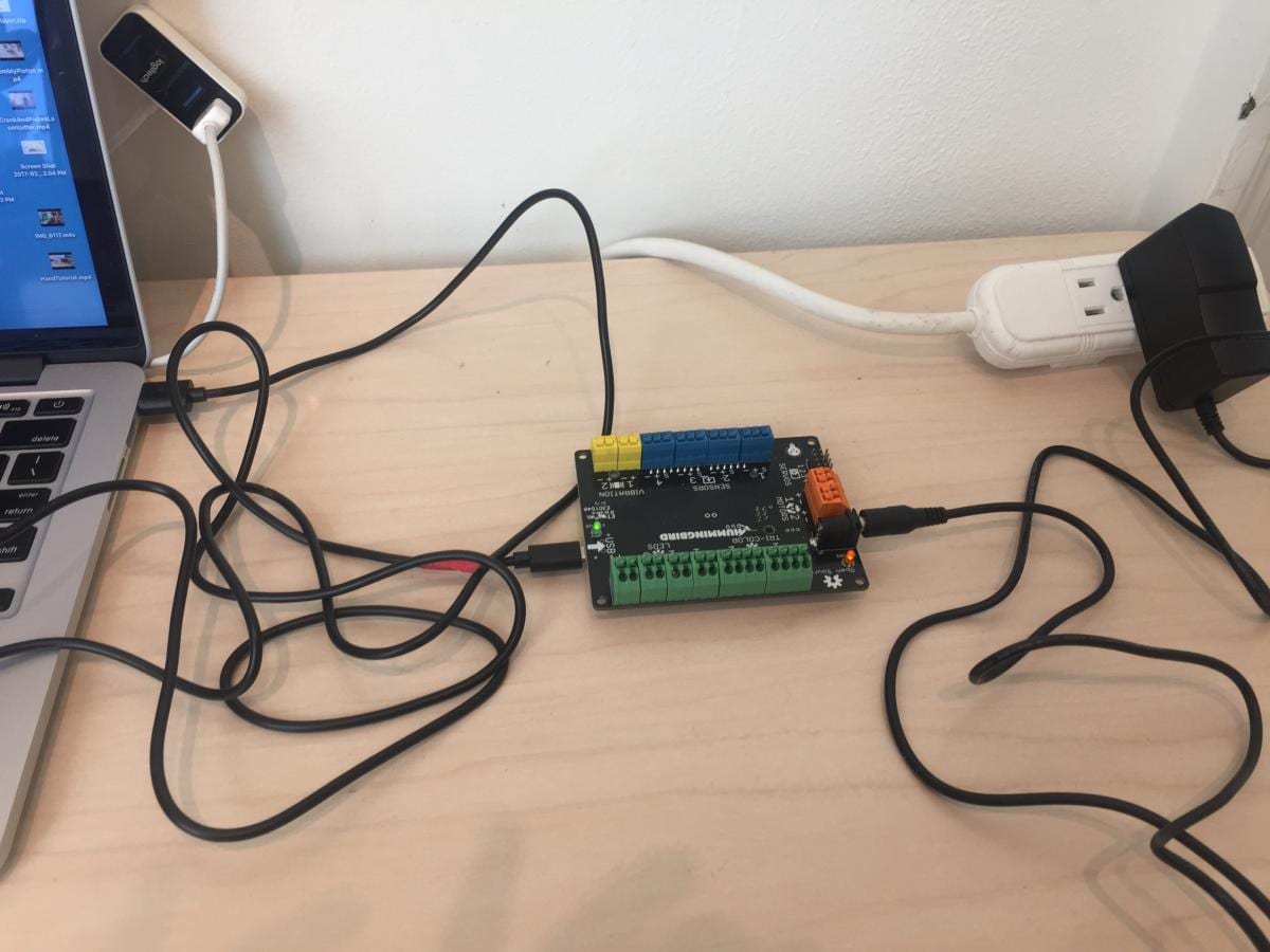
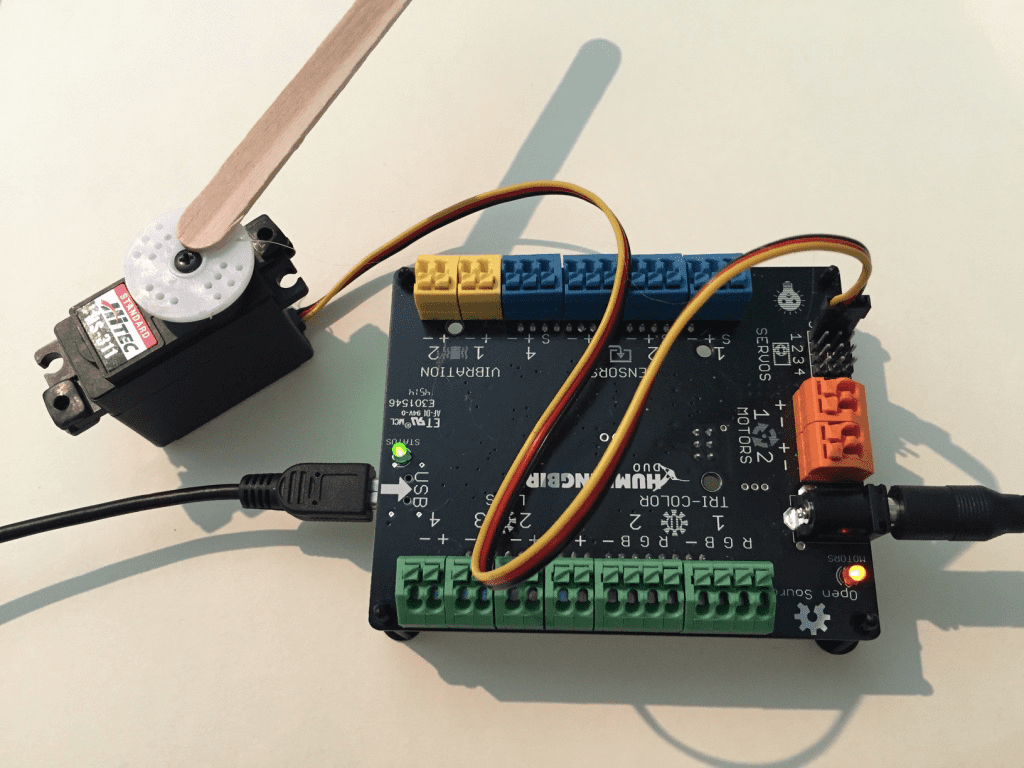
Important Note: When using the servo motor, you must also use the AC power adapter (or a battery pack). Otherwise, the Hummingbird board will not have enough power to run the motor.

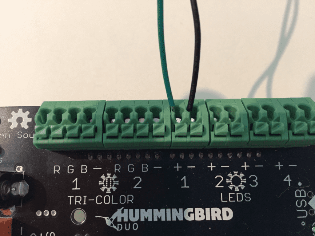
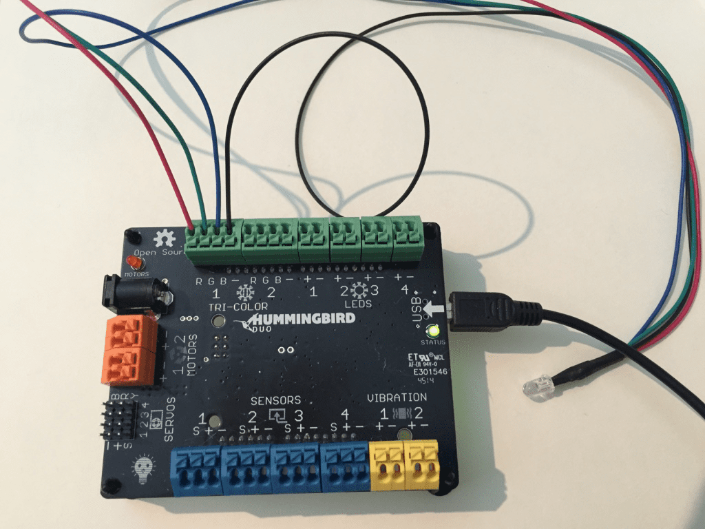
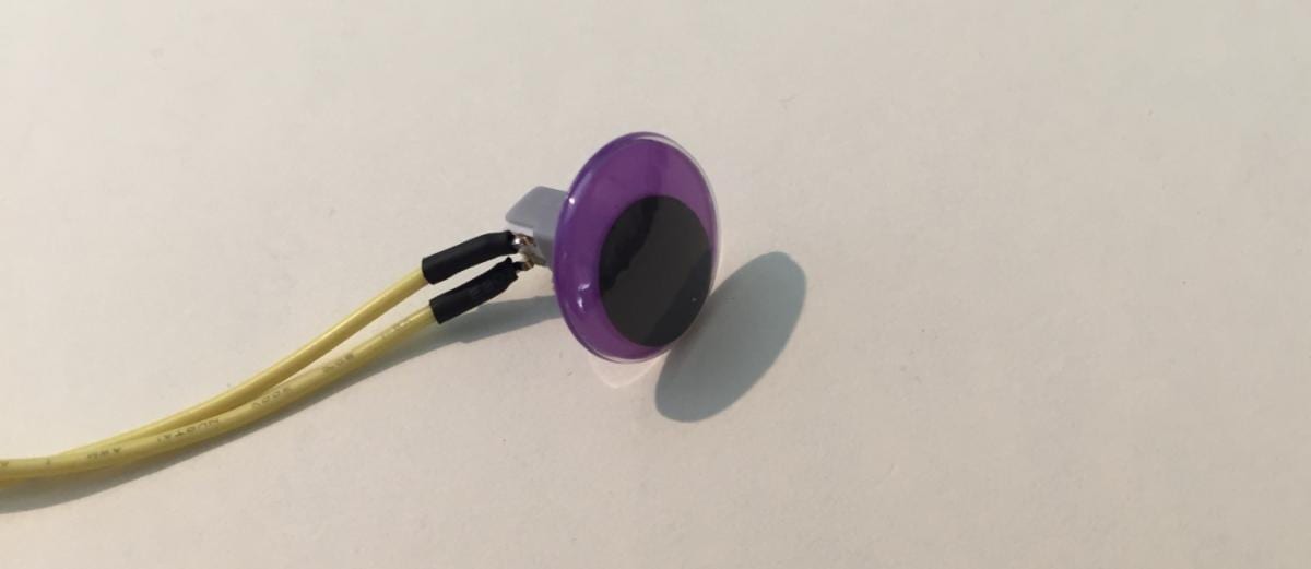
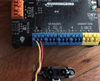
The servo motor has a small plug. This plug should be connected to one of the four sets of pins in the “SERVOS” section of the Hummingbird board. Each set of three pins is one servo port. The black wire should be connected to the ‘-’ pin, the red wire to the ‘+,’ and the yellow wire to the ‘S.’

Use hot glue to attach a popsicle stick to the white plastic circle on the servo motor.

This will help you to see the movement of the servo motor more easily. If you don’t want to use hot glue, you can tape a feather to the plastic circle.

To create an expression that uses a servo, select the correct port above the Servos label.

You can then use the slider to set the angle of the servo from 0° to 180°. The expression below sets a servo motor attached to port 1 to 90°.

To see a servo move, your sequence must contain at least two expressions with the servo at different angles (more than 10° different). For example, the sequence below contains expressions that move the servo to 60° and 120°.

Exercise 3.2

Create expressions and a sequence to move the servo repeatedly through the following angles: 0°, 90°, and 180°.

Exercise 3.3

Write expressions and a sequence to move the servo to five different angles. Make the tri-color LED a different color at each angle.

Building Tip

Before you start building with a servo, always set it to 90°. This will make sure that the servo can move both left and right once it is attached to your robot.

Gear Motors

The gear motor can be attached to either of the ports labeled “MOTORS” on the Hummingbird board. It does not matter which wire is attached to ‘+’ and which is attached to ‘-.’ When using the gear motor, you must also use the AC power adapter (or a battery pack).

Important Note: Do not cut the zip ties off your motors. Without the zip tie, the wires may break off the motor.

To create an expression that uses a gear motor, select the correct port above the Motors label. You can then use the slider to set the speed of the motor from -100 to 100. As an example, the script below sets the motor to speed 100.

Exercise 3.4

Use a small screwdriver to attach a wheel to the motor so that you can see it move more easily (or just place the wheel on the motor without using a screw). Try several speeds between 0 and 100. Describe how the speed affects the motor. Try several negative speeds. What does it mean for the speed to be negative?

Important Note: You may notice that your motor rotates clockwise for positive numbers, while your neighbor’s rotates counterclockwise for the same number. This just means that you and your neighbor chose ‘+’ and ‘-‘ differently when you connected your motors. Either way is fine!

Module 4: Adding Sound

To add sound to an expression, select the Audio option at the bottom of the Expression Builder tab. If you select Tone, you can choose a piano key to play. You can also choose the Volume of the tone and how long it will play (Duration).

If you select Speech, you can make the computer say words or phrases. Type the words in the Text box, and the computer will say them over its speakers when you play the expression.

Important Note: When you add an expression with sound to a sequence, make sure that the number of seconds for the expression is enough time for the sound to finish playing.

Exercise 4.1

Write a sequence that plays a series of tones. Set the duration of each tone to 0.25 seconds and play each expression for 0.35 seconds so that your tones are slightly separated.

Module 5: Adding a Counter

Sometimes you may want to repeat two or more expressions a certain number of times in your sequence. For example, suppose you want to turn on the gear motor, blink an LED five times, turn off the gear motor, and then blink an LED five more times. To do this, you could create a very long sequence, but it is easier to use the Counter structure.

Counter repeats the expressions inside it a certain number of times. To add a Counter to your program, click on the Counter icon in the lower-right corner of the Sequence Builder tab and drag the structure into your program.

Drag the expressions that you want to repeat inside the counter.

For example, the Counter below will repeat expressions named “Light1On” and “Light1Off.”

Next, click on the bar at the top of the Counter to choose how many time to repeat the expressions.

In the example below, the expressions will be repeated five times.

We will want to use this Counter twice in our final sequence. To make this easier, save it with the name “LightCounter.”

Create a new sequence. First, add an expression to turn on the gear motor (any speed is fine). Then add the “LightCounter” sequence. It will be located in the Sequences area on the right in the Sequence Builder tab. Add an expression to turn the gear motor off. Finally, add the “LightCounter” sequence again to get the final sequence shown below. This sequence should turn the motor on, blink an LED five times, turn the motor off, and blink an LED five more times. Try it!

Exercise 5.1

Create a Counter sequence that moves a servo back and forth four times between two different angles. How can you use this Counter within a larger sequence?

Exercise 5.2

Are you ready to use all the Hummingbird lights and motors? Write a program that includes the following:

  • At least three LEDs
  • At least two different kinds of motors
  • At least two sounds
  • At least one Counter structure

Using the Hummingbird Inputs

Module 6: Distance Sensor

The Hummingbird LEDs and motors are output devices. Scripts in Snap! send commands to these devices to make something happen. The Hummingbird sensors, on the other hand, are input devices. They send information to the Snap! program. The Snap! program can use this information to make a decision or control a light or a motor.

All of the sensors are attached to the Hummingbird in the same way. A sensor can be attached to any one of the four ports labeled “SENSORS.” Each sensor has a red wire, a black wire, and a yellow wire. The red wire should be connected to ‘+,’ the black to ‘-,’ and the yellow to ‘S.’

Exercise 6.1

Attach a distance sensor to sensor port 1 of the Hummingbird. You should also connect a single color LED to the Hummingbird. Create an expression to turn the LED on and one to turn the LED off.

The distance sensor measures the distance to the closest object. Create a new sequence and drag a Sensor block into it. This block enables the program to make a decision based on the value of a sensor.

The light sensor is selected by default. Click the drop-down menu at the top of the Sensor block to select the distance sensor. The distance sensor for the Hummigbird Duo is slightly different than the one for the original Hummingbird, so make sure to select the correct one for your kit.

The other drop-down menu in the Sensor block allows you to choose the port to which the sensor is attached. In this case, the default of port 1 is fine.

Exercise 6.2

The green bar shows you the value of the sensor. As you move an object closer to the distance sensor, you should see this bar move to the left (“Near”). Watch the value of the distance variable change as you move an object back and forth in front of the sensor. Notice that the sensor cannot detect objects very close to the sensor or very far from it. It works best in the range of 20 cm to 60 cm.

Place the expression to turn the LED on in the left side of the Sensor block. Place the expression to turn it off on the right side. Now the Sensor block will make a decision when you play the sequence. When an object is close to the distance sensor, the expression on the left will run. When the object is far from the sensor, the expression on the right will run. The dividing line between “Near” and “Far” is the blue box, which is called the threshold. You can click and drag this box to change the threshold.

When you use a Sensor block, make sure that you are in Play Loop mode. The arrows at the bottom of the left and right sides of the Sensorblock should point straight down. In this mode, the decision will be repeated over and over. When you bring an object close to the distance sensor, the expression on the left should run. When you move it away, the expression on the right should run. The CREATE Lab Visual Programmer highlights the expression that is running.

Exercise 6.3

The Sensor block checks the value of the distance sensor each time the program repeats the decision. However, the value of the sensor is not checked while the expressions inside the Sensor block are running. Change your sequence so that each expression lasts for five seconds. When you run this program, you will notice that the program does not respond quickly when you move an object toward or away from the distance sensor. What is the smallest possible wait time that you can use for an expression? This will make your program respond as quickly as possible to a change in the value of the distance sensor.

Exercise 6.4

Write a program that blinks a red light and moves a servo motor when an object is close to the distance sensor. When nothing is near the distance sensor, the light should be off and the servo should not move.

Module 7: Rotary Knob

The rotary knob is another sensor; this sensor measures how much you have turned the knob. In the CREATE Lab Visual Programmer, this sensor is called the potentiometer. In the Sensor block, you should select Potentiometer from the drop-down menu. After you have selected the correct sensor and port, you can use the Sensor block to make a decision, just like you did with the distance sensor.

Exercise 7.1

Attach the knob to sensor port 2 of the Hummingbird board. How does the green bar in the Sensor block change when you turn the knob to the left? When you turn the knob to the right?

Programming Tip

Don’t forget to set the port in the sensor block to the port on the Hummingbird board that you are actually using! If the value of the sensor is not changing as expected, be sure to check that the sensor block is reading the correct port.

Exercise 7.2

Write a program that turns a tri-color LED green and plays a sound when the knob is turned toward the left. When the knob is turned toward the right, the LED should be purple and a different sound should be played.

Exercise 7.3

Write a script that vibrates a motor when the knob is turned to the right. When the knob is turned to the left, the vibration motor should be off. Save this sequence with the name “KnobControlsVibration.” You will need it for a later exercise.

Module 8: Light Sensor

The light sensor measures the amount of light around it. This sensor is very similar to the other sensors that you have learned about. To use this sensor, select Light Sensor in the drop-down menu in the Sensor block.

Exercise 8.1

Attach the light sensor to sensor port 3 of the Hummingbird board. Watch the green bar move as you cover the light sensor with your hand and uncover it. The point halfway between the maximum and minimum values that you see is a good threshold for the light sensor. Click and drag the blue box to adjust the threshold. Make sure that the green bar moves from one side of the threshold to the other when you cover the sensor.

Exercise 8.2

Write a script that turns on a vibration motor when the light sensor detects that it is dark. Otherwise, the vibration motor should be off. Save this sequence with the name “LightControlsVibration.” You will need it for a later exercise.

You have now practiced using all the Hummingbird motors and lights, as well as three of the sensors. There are other sensors, including a temperature sensor and a sound sensor. These work very similarly to the sensors you have already used. For the sound sensor, make sure that you select the version of the sound sensor that you have (original or Duo) in the drop-down menu of the Sensor block.

Module 9: Using Multiple Sensors

The last three exercises below will give you some practice using multiple sensors. After you have completed these, you will be ready to create many exciting, unique Hummingbird robots!

One way to use multiple sensors is to create a sensor that includes two sensor blocks, one after the other. The example below shows a portion of a sequence that has a Sensor block with a light sensor and then one with the distance sensor. Notice that the duration of each expression is set to 0 seconds to make sure that the program responds as quickly as possible to both sensors.

Exercise 9.1

Write a program that uses a knob sensor to control the color of one tri-color LED and a distance sensor to control the color of a second tri-color LED.

The other way to use multiple sensors is to nest a sequence with a sensor inside another sensor block. For example, you have created two sequences called “LightControlsVibration” and “KnobControlsVibration.” You can place these sequences inside another Sensor block that uses the distance sensor. This program uses three sensors!

Exercise 9.2

Consider the program shown above. How can you turn on the vibration motor when the value of the distance sensor is above the threshold? How can you turn on the vibration motor when the distance sensor is below the threshold? Make your predictions and then test them.

Exercise 9.3

Write a program that sends the servo to four different angles based on the values of the distance and light sensors. All of the values are shown in the table below.

Distance Light Servo Angle
Greater than 20 cm Above the threshold
Greater than 20 cm Below the threshold 60°
Less than 20 cm Above the threshold 120°
Less than 20 cm Below the threshold 180°

Congratulations! You have completed Hummingbird training for the CREATE Lab Visual Programmer.

Have fun making robots!

Resources

Back to Top