Register to receive free access to all teacher materials.

l Projects
Programming Language
Any language supported by Hummingbird Duo
Subjects
Maker Tools
Grades
6-8, 9-12
Circuit Scribe is a pen that writes with conductive ink. It was developed by Electroninks. You can use it to draw circuits on paper! There are a lot of interesting things you can do with Circuit Scribe, but this tutorial will focus on how to use it with the Hummingbird. In the process, you will learn a little bit about how the Hummingbird sensors work.
Basic Circuit Scribe Circuit
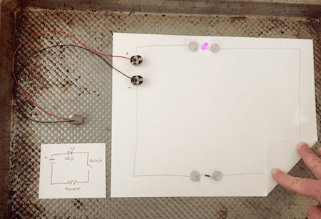
Use the Circuit Scribe to draw the circuit shown below. The circuit diagram is also shown. This circuit includes a battery (CR2032), a resistor, and an LED (no Hummingbird yet). A 200 ohm resistor was used here, but anything from 100 ohms to 50 kohms should be fine. Magnetic Circuit Scribe connectors are used to connect the battery to the circuit. You will need to place a steel sheet (in this case, a cookie sheet) behind the circuit to hold the connectors in place.
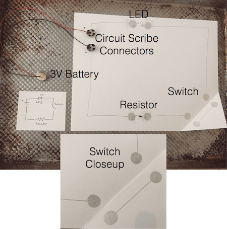
To attach the resistor and the LED to the circuit, draw two filled circles with a gap between them. Then use Scotch tape to attach the resistor or LED to these circles. It may be helpful to bend the metal legs of the components to get a larger connection area.
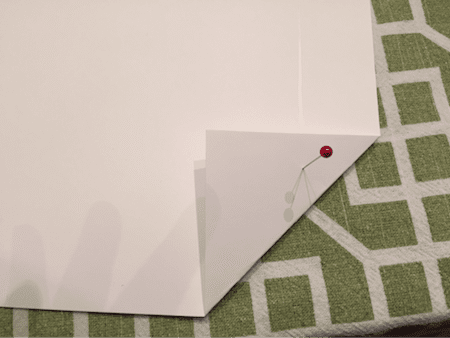
Notice that the circuit above is open at the lower right corner. Current cannot flow. When the corner of the paper is folded, the circuit is closed and current can flow. The corner of the paper is like a button that can be used to turn the LED on and off.
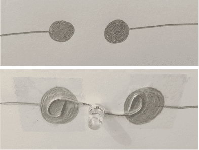
To ensure that the switch would close properly, a straight pin was used to mark the position of the circles of conductive ink, as shown below.
Adding the Hummingbird
To integrate the Hummingbird with the Circuit Scribe, first remove the battery. Use the CircuitScribe connectors to couple the ‘+’ and ‘-’ ends of the circuit to the ‘+’ and ‘-’ terminals of sensor port 1 on the Hummingbird. Make sure the Hummingbird is attached to the computer with the USB cable. Now, the Hummingbird provides power to the circuit! You should still be able to use the switch to turn the LED on and off.
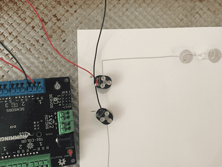
You can also use the Hummingbird to enable the computer to measure whether the switch is open or closed. Draw a new circle of conductive ink and use a third Circuit Scribe connector to couple it to the ‘S’ terminal of sensor port 1. This circle should be connected to the circuit between the resistor and the switch.
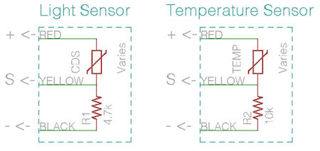
Compare the diagram below to the circuit that you have been working with. This image shows the circuit schematics for the Hummingbird light and temperature sensors. These sensors are represented by the variable resistors labelled “CDS” and “TEMP,” respectively. How are these similar to your circuit?
Programming with Circuit Scribe and the Hummingbird
In this tutorial, we will describe how to use your switch to control a motor in Scratch. However, feel free to use another programming language if you prefer!
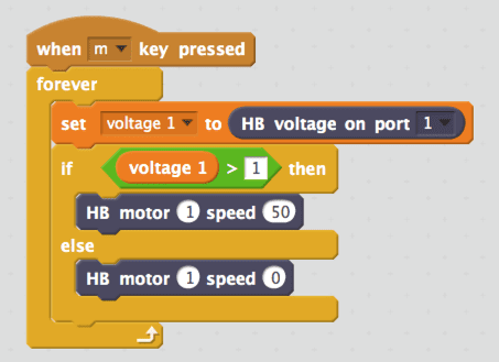
In Scratch, create a variable named voltage 1. Use the program below to set this variable equal to the voltage at the ‘S’ terminal of sensor port 1.
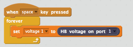
When you open and close the switch, you should see the value of voltage 1 change. When the circuit is open, the value should be close to 0 V. When the circuit is closed, the value should be larger. The exact value will vary based on the value of the resistor and the resistance of the Circuit Scribe traces. For the circuit shown here, the high value was approximately 1.5 V.
Now you can use the switch like any other Hummingbird sensor! The program below uses the switch to turn a motor on and off.
Using Multiple Switches
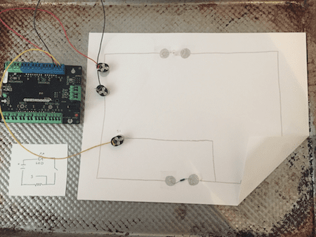
You may want to create a Hummingbird project with multiple paper switches! To reduce circuit complexity and use fewer Circuit Scribe connectors, you can use a common ‘-’ trace. Connect this trace to the ‘-’ terminal of one sensor port to ground all the sensors. This is shown in the wiring diagram below. However, each switch does need a separate power supply; the switch connected to sensor port 2 must be powered by that port. Experiment to find out what happens when you use the same ‘+’ terminal to supply power to two switches!

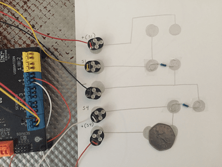
It is very helpful to test your circuit as you add switches to it. The circuit below contains two switches. A coin was used to close each switch for testing. As you add switches to your circuit, create a variable for each switch in Scratch. Use a forever loop to continually set the value of each variable to the voltage at the corresponding sensor port. Test that the voltage rises when the switch is closed.
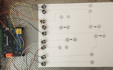
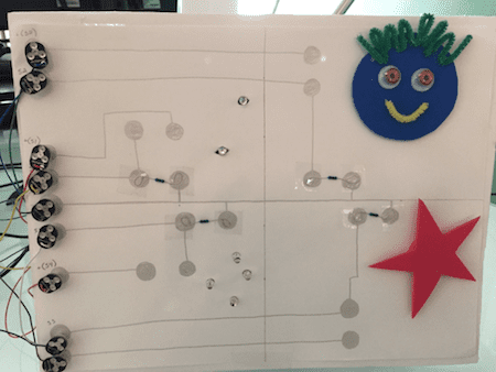
The circuit below contains four switches using a total of nine Circuit Scribe connectors. By itself, this circuit doesn’t do anything particularly interesting. It is time to add some Hummingbird motors and lights!
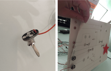
Up to this point, you have been placing your paper circuit on a metal surface. This won’t work well with the Hummingbird components, because you will want to be able to easily make holes for the wires and motors. Instead of a metal plate, you can use metal brads to keep the Circuit Scribe connectors in place.
Here is the finished project. It contains single color LEDs, tri-color LEDs, a servo motor, and a gear motor. Each of the four switches operates different components. To see this project in action, watch the video above.
What can you make by combining Circuit Scribe and the Hummingbird? Send us a picture or video of your creation!