Register to receive free access to all teacher materials.

l Projects
Print
Modeling Joints with Robotics
Use the Hummingbird Kit to construct a robotic model of a joint that uses motors to represent the contraction and extension of muscles.
Created By
Brett Slezak and Amanda Waronsky of Springale Junior/Senior High School
Programming Language
Any language supported by Hummingbird Duo
Subjects
Science
Grades
6-8
Free Teacher Materials
Objective & Learning Goals
- Students will design a robotic model that accurately demonstrates how muscles contract to cause motion at a joint.
- Students will explain the biomechanical principles of joint motion with correct identification of muscles, bones, and tendons.
- Students will collaborate with peers to build the model, write the program, and prepare a presentation within time constraints.
Standards
This project was designed to meet standard 10.1.6.B from the Pennsylvania Academic Standards for Health, Safety & Physical Education: “Identify and describe the structure and function of the major body systems.” In addition, this project is aligned with the middle school engineering standards in the Next Generation Science Standards (MS-ETS1-1, MS-ETS1-2, MS-ETS1-3, and MS-ETS1-4). This project also incorporates Common Core ELA standards in speaking (SL.7.1, SL.7.4, and SL.7.5).
Photo Gallery
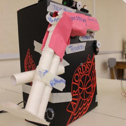
The contraction of flexor and extensor muscles to move a joint is a complex system that can be difficult for students to visualize and understand. Brett Slezak and Amanda Waronsky are using robotics to help their seventh grade students better understand the biomechanics of joint movement. They combine the health and PE classes at Springdale Junior/Senior High School to complete this project with 40 students in roughly eight 45-minute class periods. Students work in groups of three or four to construct a robotic model of a joint that uses motors to represent the contraction and extension of muscles. This project is a good opportunity for individualized learning; the complexity of the joint and the model can vary for each group.
Lesson Procedures:
- Introduce students to the biomechanical principles of joint motion. These are summarized in BiomechanicsHandout.pdf.
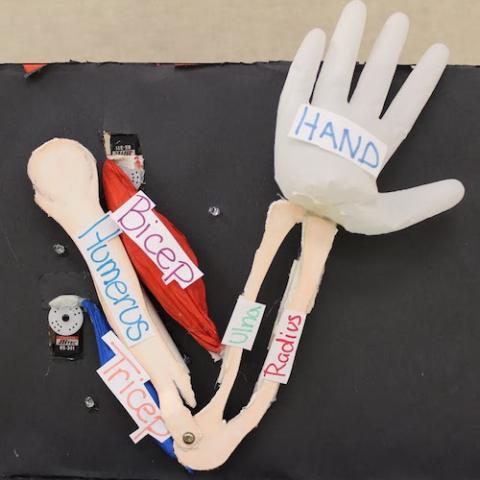
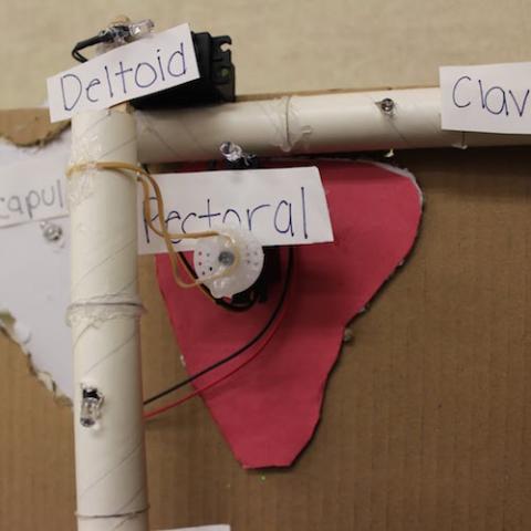
- Explain the project. Each group of students will model one of the following joints: the elbow, the knee, or the shoulder. This model should demonstrate how the muscles at this joint cause the movement of the joint. Provide a copy of the grading rubric to students.
- Each model should include at least one sensor, one motor, and one LED.
- The model should consist of recycled materials.
- The motion produced by the model must correctly illustrate the biomechanics of the joint.
- Each group must demonstrate and explain their model to the class in a 2-3 minute presentation.
- It may be helpful to show students a sample robot or a video of a sample project.
- Divide students into groups of 3 or 4.
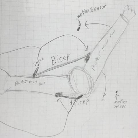
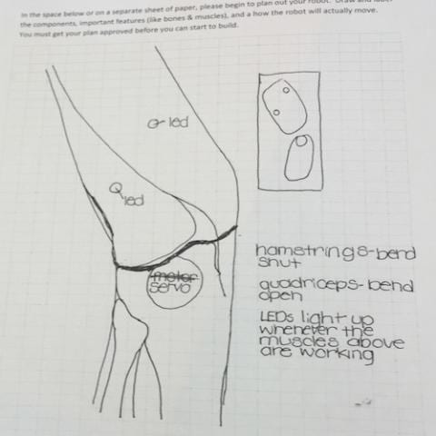
- Have each group work together to sketch their chosen joint using BiomechanicsPlanningDocument.pdf. This sketch should illustrate the parts of the joint and how it will move. Students may need to research their chosen joint in order to create a plan.
- As each group completes their sketch, meet briefly with them to determine whether their plan reflects an accurate understanding of the biomechanics of the joint. For example, students may try to move the joint by placing a servo motor directly under the joint axis (sketch of the knee shown above). This does not indicate an understanding of flexor and extensor muscles. A motor should represent a muscle or muscle group (sketch of the elbow shown above). Ideally, the model should demonstrate that muscles shorten when they contract. Each group must have their plan approved before beginning to build.
- As groups prepare to build, remind them to bring in recycled materials from home.
- To complete the project within the time constraints, students must divide the work. For example, in a group of three, one student might work on building, one on programming, and one on the group presentation. Each group can decide how to divide the work, but you may need to remind them to do so.
- Encourage groups who finish early to take their project further. Examples are given in the Extensions section.
- On the last day or two of the project, have each group present their work to the class.
Extensions
The joint choices for this project range from a hinge joint (the elbow) to a biomechanically more complex ball-and-socket joint (the shoulder). Students can be encouraged to challenge themselves by choosing a more complex joint. Grading can be adjusted so that students are not penalized for choosing a more challenging project; for example, tell students that an ambitious project that does not work perfectly can still receive a good grade.
Most students will choose to create a two-dimensional model of a joint. Students can be encouraged to take their models further by incorporating pulleys to increase the range of motion of the joint or by including additional anatomical details. As an example, the video below shows a model of the knee that includes pulleys and the cruciate ligaments (based on The Mechanics of the Knee and Prosthesis Design and a video of the knee modeled with a four-bar linkage). Another interesting extension, particularly for the shoulder joint, would be for students to make their model more three-dimensional.