
l Program
l Program

Saving Files
Setup
This module will cover how to connect, charge, and start programming your Hummingbird Bit using Snap! as the programming language. Your device must have Bluetooth capability.
Insert a micro:bit into your Hummingbird Bit Controller (you might need to push a little harder than you think!). The Hummingbird also needs a source of power, so connect it to the battery pack or AC power adapter. Connect your micro:bit to the computer with the USB cord. If you are using rechargeable batteries, check out this support article before using.
Optional step: If your micro:bit is already flashing 3 or 10 letters when powered on, you can skip this step.
Download this file and drag it onto the micro:bit. Your device should start to flash ten letters on its display. You will only need to complete this step once for each Hummingbird – as long as your device is flashing its initials, you are ready to connect via Bluetooth.
Now you have two choices. Option 1 (Chrome browser) is our preferred setup!
- Option 1 is to program the robot in the Chrome browser through snap.birdbraintechnologies.com. This website is compatible with Chromebooks as well as Mac/Windows/Linux computers. Use this option if you cannot install software on your devices. This option starts on step 6.
Jump To Chrome Browser Setup - Option 2 is to download and install the BlueBird Connector. This option has a more intuitive interface for connecting to the Hummingbird Bit, but it only works on Windows and Mac computers. This option is shown on steps 12-14.
Jump To Mac/Windows Setup
Note: Programs written in Snap! using the BlueBird Connector for Mac/Windows cannot be run on snap.birdbraintechnologies.com, and vice versa. Use this converter if you need to move a program from one platform to the other.
Chrome Browser Setup – Using snap.birdbraintechnologies.com
To use the BirdBrain Snap! web app, you must make sure the Chrome settings allow third-party cookies.
Chrome Browser Setup – Using snap.birdbraintechnologies.com
Chrome Browser Setup – Using snap.birdbraintechnologies.com
Click Find Robots. You will see a list of devices that start with BB (Hummingbird Bit), FN (Finch), or MB (micro:bit). You may see one robot or many, depending on how many are nearby. If you have downloaded the most recent BirdBrain firmware(from step 3) then your micro:bit will flash a code starting with #BB and ending in 5 numbers and letters. Look for this code in the connection menu and connect to this device. You can also use masking tape to label your Hummingbird with it’s device name for quicker identification in the future.
You will hear a sound as the Hummingbird connects, and the initials will stop flashing on the micro:bit. Once you have connected to a Hummingbird, the name of your robot will appear on the screen, and Snap! will load automatically.
Chrome Browser Setup – Using snap.birdbraintechnologies.com
If you become disconnected while programming your Hummingbird, click the expand button to see the Find Robots button and reconnect.
Chrome Browser Setup – Using snap.birdbraintechnologies.com
You can use Snap! online or offline. To use Snap! offline with the Hummingbird, install it on your Chromebook using the orange install button.
Chrome Browser Setup – Using snap.birdbraintechnologies.com
You are ready to begin programming!
Windows/Mac Setup – Using BlueBird Connector
Install the BlueBird Connector.
Windows/Mac Setup – Using BlueBird Connector
Open the BlueBird Connector and check that the bluetooth symbol has a green check beside it.
You may see one robot or many, depending on how many are nearby.
Click on the name of the robot that matches the initials on your device. The initials are the three letters that flash before the # symbol.
You will hear a sound as your device connects, and the initials will stop flashing on the device. The name of your robot should appear under Connected.
Troubleshooting Note: The BlueBird Connector must remain open in the background the entire time that you are working with the Hummingbird. If your Hummingbird disconnects, the app will notify you, and the Hummingbird will begin flashing its initials again. If this happens, return to the BlueBird Connector and reconnect it.
Windows/Mac Setup – Using BlueBird Connector
You are ready to begin programming! Click Open Snap!.
In addition to the programming tutorials on this page, we have a lot of other resources to help you work with with your Hummingbird Kit.
- Our coding cards provide printable programming help for your students.
- Our blocks document is a handy reference guide that lists all the Hummingbird blocks in Snap!.
- Our Build pages offer tutorials and inspiration for building your own robots and mechanisms.
- Our free Professional Development course ties everything together in an online course you can watch at your own pace.
Saving Files
This module will cover how to connect to the Hummingbird Bit with a USB cord and start programming in Snap!
This is legacy software that should only be used for Windows machines without the Bluetooth dongle. It is not compatible with micro:bit V2.
Install the BlueBird Connector.
Insert a micro:bit into your Hummingbird Bit Controller (you might need to push a little harder than you think!), and connect it to the computer with the USB cord. The Hummingbird also needs a source of power, so connect it to the battery pack or AC power adapter.
Download this file and drag it onto the micro:bit. Your device should start to flash three letters on its display. This file is different from the .hex file used to connect via Bluetooth.
Open the BlueBird Connector. You will hear a sound as your device connects. The name of your robot should appear under Connected.
In addition to the programming tutorials on this page, we have a lot of other resources to help you work with with your Hummingbird Kit.
- Our coding cards provide printable programming help for your students.
- Our blocks document is a handy reference guide that lists all the Hummingbird blocks in Snap!.
- Our Build pages offer tutorials and inspiration for building your own robots and mechanisms.
- Our free Professional Development course ties everything together in an online course you can watch at your own pace.
Single Color LED
Introduction
It is important to save your work frequently in Snap!. Snap! does not save automatically. This module will cover two different ways of saving your work. First, you can export your work and save it to your computer or a USB drive. If you have internet access, you can also save your work online using a Snap! cloud account.
Note: Programs written in Snap! using the BlueBird Connector for Mac/Windows cannot be run on a Chromebook, and vice versa. If you need to convert a saved program from one platform to another, you can use this online converter.
Exporting a Snap! Program
You can save your work by exporting your Snap! File and saving it to your computer, cloud storage, or a USB drive.
Go to File and then Export project.
((img class=img-responsive src=https://learn.birdbraintechnologies.com/wp-content/uploads/2019/12/pasted-image-0-62-1.png))Depending on your browser settings, the program will either be downloaded directly to your Downloads folder, or you will be asked where you want to save it. If the program is downloaded automatically, it is named HummingbirdSingleDeviceStarterProject.xml. You can find this file in your downloads folder and rename it or move it as needed. You should leave the .xml extension in the file name.
Important Note: You must export a new version of your file every time you want to save it!
Saving to a Snap! Cloud Account
If you have internet access, you can save your work in Snap! by using a cloud account. Ciick the Cloud button and then Log in to sign in to your account. You may need to set up an account if you do not already have one.
((img class=img-responsive src=https://learn.birdbraintechnologies.com/wp-content/uploads/2019/12/pasted-image-0-64-1.png))Once you are logged in, choose Save As on the File menu.
((img class=img-responsive src=https://learn.birdbraintechnologies.com/wp-content/uploads/2019/12/pasted-image-0-65-1.png))Give your program a descriptive name and make sure to select the Cloud option. Then click Save.
((img class=img-responsive src=https://learn.birdbraintechnologies.com/wp-content/uploads/2019/12/pasted-image-0-66-1.png))Important Note: Make sure to save your work frequently by going to File and then Save!
((img class=img-responsive src=https://learn.birdbraintechnologies.com/wp-content/uploads/2019/12/pasted-image-0-67-1.png))Loading from a Snap! Cloud Account
To open a file you saved previously, first log in to your Snap! cloud account. Then go to File and then Open.
((img class=img-responsive src=https://learn.birdbraintechnologies.com/wp-content/uploads/2019/12/pasted-image-0-68-1.png))Select your file in the window that pops up. Be sure to select the Cloud option.
((img class=img-responsive src=https://learn.birdbraintechnologies.com/wp-content/uploads/2019/12/pasted-image-0-69-1.png))Tri-Color LED
This module will cover how to connect to the Hummingbird Bit via Bluetooth and start programming in Snap!. Your computer must have Bluetooth capability to program the Hummingbird in Snap!.
Using a Chromebook? Can’t download software? Setup your Hummingbird Bit here.
Please note that there is no sound in these videos.
Install the BlueBird Connector.
Insert a micro:bit into your Hummingbird Bit Controller (you might need to push a little harder than you think!), and connect it to the computer with the USB cord. The Hummingbird also needs a source of power, so connect it to the battery pack or AC power adapter. If you are using rechargeable batteries, check out this support article before using.
Optional step: If your micro:bit is already flashing 3 or 10 letters when powered on, you can skip this step.
Download this file and drag it onto the micro:bit. Your device should start to flash ten letters on its display. You will only need to complete this step once for each Hummingbird – as long as your device is flashing its initials, you are ready to connect via Bluetooth.
After dragging the file onto the micro:bit, remove the USB cord. You won’t need it to use Snap!
Open the BlueBird Connector and check that the bluetooth symbol has a green check beside it.
You may see one robot or many, depending on how many are nearby.
Click on the name of the robot that matches the initials on your device. The initials are the three letters that flash before the # symbol.
You will hear a sound as your device connects, and the initials will stop flashing on the device. The name of your robot should appear under Connected.
Troubleshooting Note: The BlueBird Connector must remain open in the background the entire time that you are working with the Hummingbird. If your Hummingbird disconnects, the app will notify you, and the Hummingbird will begin flashing its initials again. If this happens, return to the BlueBird Connector and reconnect it.
In addition to the programming tutorials on this page, we have a lot of other resources to help you work with with your Hummingbird Kit.
- Our coding cards provide printable programming help for your students.
- Our blocks document is a handy reference guide that lists all the Hummingbird blocks in Snap!.
- Our Build pages offer tutorials and inspiration for building your own robots and mechanisms.
- Our free Professional Development course ties everything together in an online course you can watch at your own pace.
LED Screen
This module will cover how to connect, charge, and start programming your Hummingbird Bit using Snap! as the programming language. You will program the robot in the Chrome browser through snap.birdbraintechnologies.com. This website is compatible with Chromebooks as well as Mac/Windows/Linux computers, but your device must have Bluetooth capability.
Note: Programs written in Snap! using the BlueBird Connector for Mac/Windows cannot be run on snap.birdbraintechnologies.com, and vice versa. Use this converter if you need to move a program from one platform to the other.
Insert a micro:bit into your Hummingbird Bit Controller (you might need to push a little harder than you think!). The Hummingbird also needs a source of power, so connect it to the battery pack or AC power adapter. Connect your micro:bit to the computer with the USB cord. If you are using rechargeable batteries, check out this support article before using.
Optional step: If your micro:bit is already flashing 3 or 10 letters when powered on, you can skip this step.
Download this file and drag it onto the micro:bit. Your device should start to flash ten letters on its display. You will only need to complete this step once for each Hummingbird – as long as your device is flashing its initials, you are ready to connect via Bluetooth.
Click Find Robots. You will see a list of devices that start with BB (Hummingbird Bit), FN (Finch), or MB (micro:bit). You may see one robot or many, depending on how many are nearby. If you have downloaded the most recent BirdBrain firmware(from step 3) then your micro:bit will flash a code starting with #BB and ending in 5 numbers and letters. Look for this code in the connection menu and connect to this device. You can also use masking tape to label your Hummingbird with it’s device name for quicker identification in the future.
You will hear a sound as the Hummingbird connects, and the initials will stop flashing on the micro:bit. Once you have connected to a Hummingbird, the name of your robot will appear on the screen, and Snap! will load automatically.
In addition to the programming tutorials on this page, we have a lot of other resources to help you work with with your Hummingbird Kit.
- Our coding cards provide printable programming help for your students.
- Our blocks document is a handy reference guide that lists all the Hummingbird blocks in Snap!.
- Our Build pages offer tutorials and inspiration for building your own robots and mechanisms.
- Our free Professional Development course ties everything together in an online course you can watch at your own pace.
Position Servo
This module will show you how to use a single color LED with the Hummingbird Bit. A single color LED is a small light with two wires. The colored wire shows the color of the LED. The Hummingbird kit comes with red, green, and yellow LEDs.
Please note that there is no sound in these videos.
The Hummingbird LED block is used to control a single color LED. To use this block, set the port of the LED to 1, 2, or 3 (Snap! defaults to port 1) and the brightness of the LED from 0% to 100%.
When the space bar is pressed, the Hummingbird LED is set to full brightness. Since the LED was never programmed to turn off, the light stays on at full brightness.
Reflect: What do you think would happen if you set the LED to 50% instead of 100%?
Put the Hummingbird LED block into a repeat forever loop. Add a wait block, a second Hummingbird LED block, and another wait block to the forever loop. The wait block stops the program for a number of seconds.
Each time through the loop, the program turns the LED on, pauses, turns the LED off, and pauses again. The forever loop repeats this process over and over.
Reflect: What do you think would happen if the bottom wait block was not there?
Rotation Servo
This module will show you how to use a tri-color LED with the Hummingbird Bit. A tri-color LED is a small light with four wires. The tri-color LED actually has three tiny lights inside it. One is red, one is green, and one is blue. You can combine different amounts of red, green, and blue light to make different colors.
Please note that there is no sound in these videos.
Use the terminal tool to plug a tri-color LED into TRI-COLOR port 1 on the Bit. The red wire connects to ‘R,” the green to ‘G,’, the blue to ‘B,’ and the black to ‘-.’
The Hummingbird Tri-LED block is used to control a tri-color LED. To use this block, set the port of the LED to 1 or 2 (Snap! defaults to port 1) and the amount of red, green, and blue from 0% to 100%.
When the space bar is pressed, red is set to full brightness. Since the tri-LED was never programmed to turn off, the red stays on at full brightness.
Reflect: What do you think would happen if you set both red and blue to 100?
Put the Hummingbird Tri-LED block into a repeat forever loop. Add a wait block, a second Hummingbird Tri-LED block, and a second wait block to the forever loop. The wait block stops the program for a number of seconds.
Each time through the loop, the program turns the LED red, pauses, turns the LED blue, and pauses again. The forever loop repeats this process over and over.
Reflect: How can you use a tri-color LED in a robot?
Buzzer
In this module, you will learn to display icons and patterns on the micro:bit screen.
Please note that there is no sound in these videos.
When the space bar is pressed, the micro:bit Display is set to the image you created. Since the display was never programmed to turn off, the image remains on the screen.
Reflect: How would you change this code to display a different image?
Put the micro:bit Display block into a repeat forever loop. Add a wait block, a second micro:bit Display block, and a second wait block to the forever loop. The wait block stops the program for a number of seconds.
Create a face with a different expression in the second micro:bit Display block.
Each time through the forever loop, the program shows the first expression, pauses, shows the second expression and pauses again. The forever loop repeats this process over and over.
Reflect: How would you change the code to show 3 different expressions on the micro:bit?
Sound
In this module, you will learn to use the position servo. The position servo is a motor that moves to a particular angle. The Hummingbird position servo can move to any angle from 0° to 180°.
Hummingbird Base Kit users have an FS90 Micro Servo that works the same as the servo in these modules.
Please note that there is no sound in these videos.
Plug in the position servo to SERVOS port 1 on the Bit. Make sure the black wire is aligned to ‘-,’ the red wire to ‘+,’ and the white wire to ‘S.’
The Hummingbird Position Servo block is used to control the position servo. To use this block, set the port of the servo to 1, 2, 3, or 4 (Snap! defaults to port 1) and the angle from 0° to 180°.
When the space bar is pressed, the Hummingbird Position Servo is set to 90°. Since the servo was not programmed to move to any other position, it does not move again.
Reflect: Why do you think the position servo moves once, then stops at 90°? Would the servo move if it was already at 90° before you start the program?
Put the Hummingbird Position Servo in a repeat forever loop. Add a wait block, a second Hummingbird Position Servo block, and a second wait block to the forever loop. The wait block stops the program for a number of seconds.
Each time through the loop, the program moves the servo to 90°, pauses, moves the servo to 0°, and pauses again. The forever loop repeats this process over and over.
Reflect: How would the movement of the servo change if the wait blocks were set to .5 seconds instead of 1 second?
Light Sensor
In this module, you will learn to use the rotation servo. The rotation servo is a motor that can rotate at different speeds.
The rotation servo is not included in the Hummingbird Bit Base Kit.
Please note that there is no sound in these videos.
Plug in the rotation servo to SERVOS port 1 on the Bit. Make sure the black wire is aligned to ‘-,’ the red wire to ‘+,’ and the white wire to ‘S.’
The Hummingbird Rotation Servo block is used to control the rotation servo. To use this block, set the port of the servo to 1, 2, 3, or 4 (Snap! defaults to port 1) and the speed from -100% to 100%.
When the space bar is pressed, the Hummingbird Rotation Servo is set to full speed. Since the servo was not programmed to move to stop, it keeps spinning.
Reflect: What would happen if you set the speed to -100% instead?
Put the Hummingbird Rotation Servo in a repeat forever loop. Add a wait block, a second Hummingbird Rotation Servo block, and a second wait block to the forever loop. The wait block stops the program for a number of seconds.
Each time through the loop, the program turns the motor on, pauses, turns the motor off, and pauses again. The forever loop repeats this process over and over.
Reflect: What do you think would happen if you changed the speed in the second Hummingbird Rotation Servo block to 40 instead of 0?
Dial Sensor
This module will show you how to program the buzzer output on the Hummingbird Bit. The buzzer can be used to create different musical tones that come directly from the Hummingbird controller board. The range of the buzzer is 32 to 135. This range uses the same MIDI note numbers as Scratch.
Please note that there is no sound in these videos.
From the Control folder drag out a when space key pressed block. From the Sound folder, drag out a Hummingbird Play Note __ for __ beats block and attach to a when space key pressed block. Change the timing to last for 1 beat. Drag out a second Hummingbird Play Note block and change the note and the beat value. Drag out a third Hummingbird Play Note block and change the note and the beat value.
The range of the buzzer is 32 to 135. These numbers are MIDI note numbers.
The notes you’ve programmed will play for 1 beat, one right after another. In music, the “beat” represents how long a note will play. We’ll learn to speed this up and slow this down next.
Reflect: How could you make the notes play for longer?
To make the notes play faster or slower, use the set tempo to bpm block, located in the Sound folder. Insert the set tempo to bpm block into the top of your script.
The “tempo” is the speed of a song. It is measured in beats per minute (bpm). Snap! defaults to 60 bpm. Change the tempo by clicking the white oval and typing in a new tempo.
Using a bit of math, we can figure out that a song with 120 bpm has beats that last half a second (120 bpm / 60 seconds in a minute = 2 beats in each second). Click the white oval to change the bpm and see how that affects the speed of the notes.
Reflect: What would you set the bpm to make a song where each beat = 1 second?
Next, drag out 2 rest for __ beats block, located in the Sound folder. Place one rest for __ beats block after each Hummingbird Play Note blocks. These blocks will cause there to be a silence, called a “rest.” Click the white oval to adjust the length of each rest.
The notes you’ve programmed will now play with silences or “rests” in between them. You can now program your Hummingbird to play any song at any tempo!
Distance Sensor
Introduction
In this module, you will learn how to record and play sounds with Snap! and use the text-to-speech blocks. This will enable you to use Snap! to play recorded sounds, such as your favorite song or a voice reading a story or poem. These sounds will play through the computer itself, rather than through the Hummingbird. You will also learn to use the text-to-speech blocks to make the computer read text that you type in!
Recording Sound
Before you can play a sound in Snap!, you need to add it to your project. To import a sound or record one, select the Sounds tab.
((img class=img-responsive src=https://learn.birdbraintechnologies.com/wp-content/uploads/2020/10/SnapStep7-5_image1.png))To import a sound, simply drag a sound file from your computer into the Sounds area.
To record a sound, click the red circle in the Sounds area. If you have trouble recording a sound in Snap!, you can use an online recorder such as this one, and then download the file and drag it into the Sounds area.
Once you have imported or recorded a sound, it will show up in the Sounds area.
((img class=img-responsive src=https://learn.birdbraintechnologies.com/wp-content/uploads/2020/10/image8-7-768x401.png))CHALLENGE
Find or record an mp3 of a favorite song and place it in the Sounds area of Snap!.
Playing Sounds
Once you have added a sound to Snap!, you can play it using the play sound or play sound until done blocks from the Sound menu.
((img class=img-responsive src=https://learn.birdbraintechnologies.com/wp-content/uploads/2020/10/image11-6.png))The play sound block will start the sound and then move immediately to the next line in the program. For example, when you run this program, the light comes on as soon as you start the sound.
((img class=img-responsive src=https://learn.birdbraintechnologies.com/wp-content/uploads/2020/10/image10-7.png))The play sound until done block will pause the program until the sound is complete. That means that when you run this program, the light will not come on until the “Hokey Pokey” has finished.
((img class=img-responsive src=https://learn.birdbraintechnologies.com/wp-content/uploads/2020/10/image12-6.png))If you need to, you can use the stop all sounds block to stop a sound in the middle.
((img class=img-responsive src=https://learn.birdbraintechnologies.com/wp-content/uploads/2020/10/image7-7.png))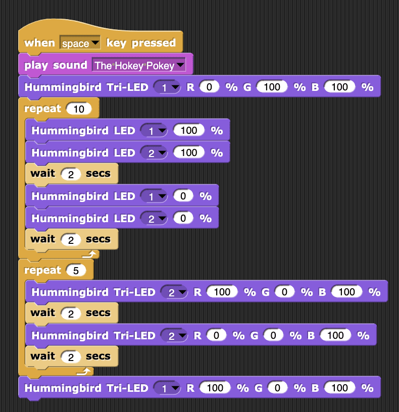
Speaking Text
Snap! also includes blocks to enable the computer to speak text aloud through the speakers. To load these blocks, go to File/Libraries….
((img class=img-responsive src=https://learn.birdbraintechnologies.com/wp-content/uploads/2020/10/snapsound1-768x413.png))In the pop-up that appears, select Text to Speech and then click Import.
((img class=img-responsive src=https://learn.birdbraintechnologies.com/wp-content/uploads/2020/10/snapsound2-768x680.png))Two speak blocks will appear on the Sound menu. The speak block starts speaking and moves immediately to the next line in the program, while the speak and wait block pauses the program until all the text has been spoken.
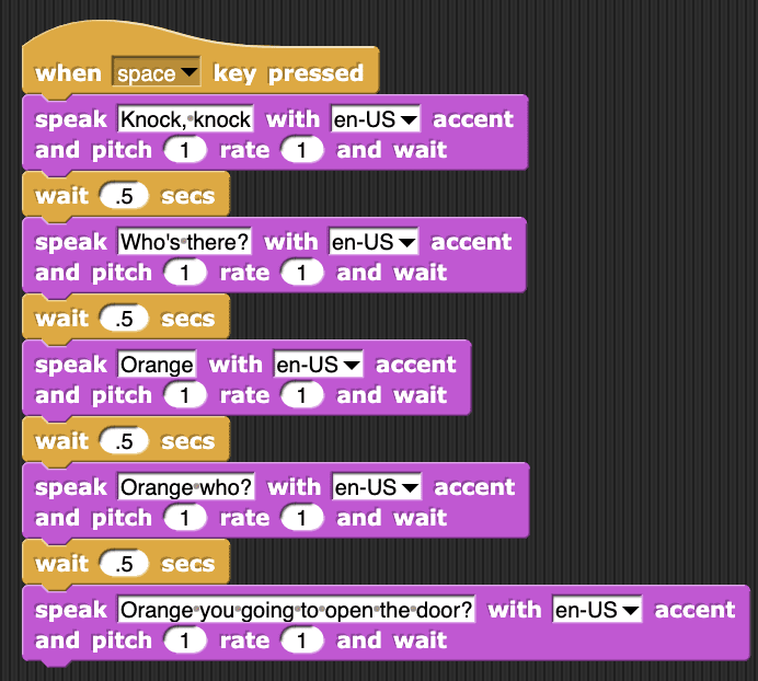
((img class=img-responsive src=https://learn.birdbraintechnologies.com/wp-content/uploads/2020/10/image4-6.png))To use a speak block, enter the text you want the computer to say. If you enter text in a language other than English, you will need to choose a different accent. The pitch parameter changes the sound of the voice that speaks the text, and the rate parameter changes the speed of the voice that speaks the text. For example, this program makes the computer announce what the Hummingbird will do before it turns the motor on.
((img class=img-responsive src=https://learn.birdbraintechnologies.com/wp-content/uploads/2020/10/image2-8.png))CHALLENGE
Write a program to make the computer tell a joke. Can you use the Hummingbird to illustrate your joke?
Click Here to see example code.
Sound Sensor
This module will show you how to use a light sensor as an input with the Hummingbird Bit. A light sensor is a component that collects data based on how much light surrounds the sensor. The range of the light sensor is 0 to 100.
This module assumes that you have already completed the single color LED module.
Please note that there is no sound in these videos.
Plug a sensor into your board. Any Hummingbird sensor can be connected to any of the three ports labelled “SENSORS” on the Bit. The yellow wire connects to ‘S,’ the red to ‘+,’ and the black to ‘-.’
Find the Hummingbird Sensor block under the Sensing folder. Use the drop-down menu to select “Light.”
To see the value of the sensor in Snap!, simply click on the Hummingbird Sensor block.
Reflect: How can you make the value of the sensor higher or lower?
The Hummingbird Sensor block measures the value of the light sensor and sets the LED brightness to that value.
Reflect: In this program, the micro:bit runs the Hummingbird LED block about 25 times per second. What do you think would happen if you added a pause block to the forever loop?
Your light sensor value can be used to make decisions. To turn on an LED when the value of the sensor is low, use an if else block from the Control folder. This block requires a comparison block, which is in the Operators folder.
This program compares the value of the light sensor to 10. If the sensor value is less than 10, the program runs the block inside the if section of the if else, and the LED turns on. When the sensor value is greater than 10, the program runs the block inside the else section, turning the LED off.
Can you make an LED turn on and off with a different sensor? Disconnect the sensor you’ve been using and connect a new sensor. Use the drop-down menu in the Hummingbird Sensor block to make the block match your new sensor.
Buttons
This module will show you how to use a dial sensor as an input with the Hummingbird Bit. A dial sensor is a component that collects data based on how much you rotate the knob. The range of the dial sensor is 0 to 100.
This module assumes that you have already completed the single color LED module.
Please note that there is no sound in these videos.
Plug a sensor into your board. Any Hummingbird sensor can be connected to any of the three ports labelled “SENSORS” on the Bit. The yellow wire connects to ‘S,’ the red to ‘+,’ and the black to ‘-.’
Find the Hummingbird Sensor block under the Sensing folder. Use the drop-down menu to select “Dial.”
To see the value of the sensor in Snap!, simply click on the Hummingbird Sensor block.
Reflect: How can you make the value of the sensor higher or lower?
The Hummingbird Sensor block measures the value of the light sensor and sets the LED brightness to that value.
Reflect: In this program, the micro:bit runs the Hummingbird LED block about 25 times per second. What do you think would happen if you added a pause block to the forever loop?
Your dial sensor value can be used to make decisions. To turn on an LED when the value of the sensor is high, use an if else block from the Control folder. This block requires a comparison block, which is in the Operators folder.
This program compares the value of the dial sensor to 50. If the sensor value is greater than 50, the program runs the block inside the if section of the if else, and the LED turns on. When the sensor value is less than 50, the program runs the block inside the else section, turning the LED off.
Can you make an LED turn on and off with a different sensor? Disconnect the sensor you’ve been using and connect a new sensor. Use the drop-down menu in the Hummingbird Sensor block to make the block match your new sensor.
Accelerometer
This module will show you how to use a distance sensor as an input with the Hummingbird Bit. A distance sensor is a component that collects data based on how close or far you are to the sensor. The range of the distance sensor is 1 to 260 cm.
The distance sensor is not included in the Hummingbird Bit Base Kit.
This module assumes that you have already completed the single color LED module.
Please note that there is no sound in these videos.
Plug a sensor into your board. Any Hummingbird sensor can be connected to any of the three ports labelled “SENSORS” on the Bit. The yellow wire connects to ‘S,’ the red to ‘+,’ and the black to ‘-.’
Find the Hummingbird Sensor block under the Sensing folder. Use the drop-down menu to select “Distance.”
To see the value of the sensor in Snap!, simply click on the Hummingbird Sensor block.
Reflect: How can you make the value of the sensor higher or lower?
The Hummingbird Sensor block measures the value of the light sensor and sets the LED brightness to that value.
Reflect: In this program, the micro:bit runs the Hummingbird LED block about 25 times per second. What do you think would happen if you added a pause block to the forever loop?
Your distance sensor value can be used to make decisions. To turn on an LED when the value of the sensor is low, use an if else block from the Control folder. This block requires a comparison block, which is in the Operators folder.
This program compares the value of the distance sensor to 15. If the sensor value is less than 15, the program runs the block inside the if section of the if else, and the LED turns on. When the sensor value is greater than 15, the program runs the block inside the else section, turning the LED off.
Can you make an LED turn on and off with a different sensor? Disconnect the sensor you’ve been using and connect a new sensor. Use the drop-down menu in the Hummingbird Sensor block to make the block match your new sensor.
Compass
This module will show you how to use a sound sensor as an input with the Hummingbird Bit. A sound sensor is a component that collects data based on how much sound surrounds the sensor. The range of the sound sensor is 0 to 100.
The sound sensor is not included in the Hummingbird Bit Base Kit.
This module assumes that you have already completed the single color LED module.
Please note that there is no sound in these videos.
Plug a sensor into your board. Any Hummingbird sensor can be connected to any of the three ports labelled “SENSORS” on the Bit. The yellow wire connects to ‘S,’ the red to ‘+,’ and the black to ‘-.’
Find the Hummingbird Sensor block under the Sensing folder. Use the drop-down menu to select “Sound.”
To see the value of the sensor in Snap!, simply click on the Hummingbird Sensor block.
Reflect: How can you make the value of the sensor higher or lower?
The Hummingbird Sensor block measures the value of the light sensor and sets the LED brightness to that value.
Reflect: In this program, the micro:bit runs the Hummingbird LED block about 25 times per second. What do you think would happen if you added a pause block to the forever loop?
Your sound sensor value can be used to make decisions. To turn on an LED when the value of the sensor is high, use an if else block from the Control folder. This block requires a comparison block, which is in the Operators folder.
This program compares the value of the sound sensor to 70. If the sensor value is greater than 70, the program runs the block inside the if section of the if else, and the LED turns on. When the sensor value is less than 70, the program runs the block inside the else section, turning the LED off.
Can you make an LED turn on and off with a different sensor? Disconnect the sensor you’ve been using and connect a new sensor. Use the drop-down menu in the Hummingbird Sensor block to make the block match your new sensor.
Multiple Devices
This module will show you how to program the A and B buttons on the micro:bit to control the single color LED output of the Hummingbird Bit. The micro:bit’s A and B buttons can be used as inputs. Pressing them can be an “event” to trigger other actions.
This module assumes that you have already completed the single color LED module.
Please note that there is no sound in these videos.
Plug in a single color LED. The A and B buttons are located on the face of the micro:bit. They can be pressed one at a time or together.
From the Control folder, drag out a when space key pressed, and attach a forever loop. Drag an if statement into the forever loop. From the Sensing folder, nest a micro:bit Button A block in the hexagon space of the if statement. From the Looks folder, drag a Hummingbird LED block into the if statement and set it to 100%.
The A button being pressed causes the Hummingbird LED to turn on.
Reflect: How could you use the A button to turn a tri-color LED red?
Duplicate the if micro:bit Button A loop and insert it into the forever loop below the first one. Use the drop down menu to change Button A to Button B. Program the Hummingbird LED to turn off when the B button is pressed.
micro:bit V2 Sensors
This module will show you how to use the accelerometer as an input to control the tri-color LED from the Hummingbird. The range of the x, y, and z variables on the accelerometer is -10 to +10 m/s^2.
This module assumes that you have already completed the tri-color LED module.
Please note that there is no sound in these videos.
From the Control folder, drag out a when space key pressed, forever loop, and if statement block, and connect them with the if statement inside the forever loop.
From the Sensing folder, nest a micro:bit Screen Up block into the hexagon space in the if statement. Use the drop down menu to select “Shake.”
Drag out 2 Hummingbird Tri-LED blocks from the Looks folder and 1 wait block from the Control folder. Write a program to turn the tri-color LED red, wait 1 second, and turn off when the micro:bit is shaken.
When you shake the Hummingbird controller board, your tri-color LED will turn red for 1 second, then turn off.
Reflect: How could you make the tri-color LED blink red and blue 3 times when the micro:bit is shaken, then turn off? (Hint: look in the Control folder for a loop!)
You can also tilt your Hummingbird Bit in different directions to change colors of the tri-color LED.
First, delete the wait and second Hummingbird Tri-LED blocks. Select the drop down menu in the micro:bit Shake block, and change it to read “micro:bit Logo Up.” Duplicate the if statement. Then, click the second drop down menu to select “micro:bit Logo Down.” Change the second Hummingbird Tri-LED to 100% green.
When you tilt the Hummingbird Bit controller forward and back, the tri-color LED will change color from red to green.
Reflect: How could you make this code control a position servo to go from 0 to 180 degrees?
While we’ve been using the accelerometer as an event up to this point, you can also use the accelerometer’s value to slowly alter a component by nesting it, which you can also do with sensors.
First, save 1 Hummingbird Tri-LED block, but delete everything else inside the forever loop. Drag a multiplication block from the Operators folder. Nest this block into the white oval next to “R” in the Hummingbird Tri-LED block. Type 10 into the first space in the multiplication block.
Nest a micro:bit Accelerometer X block from the Sensing folder into the second space in the multiplication block. This accelerometer can measure front to back movement (called x), side to side movement (called y), and up and down movement (called z).
Write a program that:
– Makes the x variable of the accelerometer control the brightness of the red of the tri-color LED.
– Makes the y variable of the accelerometer control the brightness of the blue of the tri-color LED.
– Makes the z variable of the accelerometer control the brightness of the green of the tri-color LED.
Variables
This module will show you how to use the compass as an input to control the movement of a Hummingbird position servo. The range of the compass is 0° to 359°.
This module assumes that you have already completed the position servo module.
Please note that there is no sound in these videos.
First, we must calibrate the compass. To do this, click the purple compass icon next to your Hummingbird’s name in the Bluebird Connector App. When prompted, tilt your Hummingbird every direction in the air. If successfully calibrated, a check mark will appear on both the LED screen and next to your Hummingbird’s name. If unsuccessful, try again.
Check your Hummingbird’s calibration by dragging out a micro:bit Compass block from the Sensing folder. Click the block to read the sensor value. Redirect your Hummingbird and click the block again. Repeat this process to see the different headings, from 0-360º.
Reflect: What number represents South?
From the Control folder, drag out a when space key pressed block and a forever loop. From the Motion folder, drag a Hummingbird Position Servo block into the forever loop. Nest the micro:bit Compass block into the Hummingbird Position Servo block.
The position servo will now rotate to match the compass heading. Although the range of the compass is 0°-359°, the position servo will stop at 180 degrees, because the range of the position servo is 0°-180°.
Reflect: How could you use the compass to control the brightness of a single color LED?
The compass value can also be used to make decisions. We will now set your position servo to either 0 or 180 degrees based on the compass value.
First, drag the micro:bit Compass and Hummingbird Position Servo blocks apart and outside of the forever loop. Drag an if else block from the Control folder into the forever loop. Nest a less than block from the Operators folder into the hexagon space of the if else block. Nest the micro:bit Compass block into the first space in the less than block. Set the threshold to 180 degrees.
Drag the Hummingbird Position Servo block into the first open space of the if else block and set it to “0.” Drag another Hummingbird Position Servo block into the second open space of the if else block and set it to “180.”
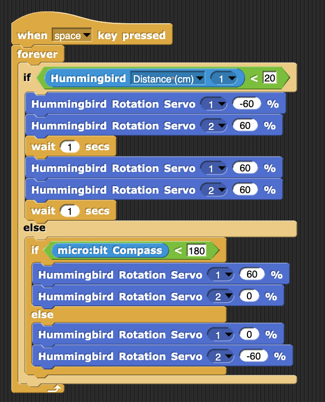
This program compares the value of the compass to 180. If the compass value is less than 180 (indicating west), the position servo is set to 0 degrees. When the compass value is greater than 180 (indicating east), the position servo is set to 180 degrees.
Reflect: How could you use a similar code to turn a tri-color LED red and blue based on the value of the compass?
Rover: Driving and Avoiding Obstacles
This module will show you how to connect multiple devices through the Bluebird Connector App. It will also show you how to wirelessly control the outputs of one Hummingbird with the inputs of another. For this module, you will need 2 Hummingbird Bit boards*, 1 tri-color LED, and 1 dial sensor. This module assumes that you have already completed the tri-color LED, buttons, and sensor modules.
If you have saved a program for a single Hummingbird and you would like to extend it to use multiple Hummingbirds, you can use this online converter.
*In steps 2-7, you will be using a micro:bit by itself without a Hummingbird controller board. To power this micro:bit, you can either use a AAA battery pack or the USB cord included in your kit.
Please note that there is no sound in these videos.
Plug in the tri-color LED into port 1. You will also need a separate micro:bit unplugged from a Hummingbird, which you can power by a USB cable or AAA battery pack (not included). We will be using a battery pack.
We will begin by connecting 2 devices. We will first be connecting a Hummingbird Bit and also a micro:bit by itself.
This step will follow how to connect two devices in the BlueBird Connector. The following step will cover how to connect two devices using the BirdBrain Snap! web app.
If you are using the BlueBird Connector, select the Find Robots button. Select the two devices you’re using by clicking the + icon. Connect the micro:bit first. Then connect the Hummingbird. The process of connecting them can take a couple seconds. Open Snap!
If you are using the BirdBrain Snap! web app, first connect the micro:bit. The name of the micro:bit will start with the letters MB. You will not hear a sound as the micro:bit connects, but it will stop flashing letters on the display.
Then click the expand button. Click Find Robots and select the Hummingbird. The name of the Hummingbird will start with the letters BB.
Both devices should show up as connected. The micro:bit will be labeled with an ‘A’ and the Hummingbird with a ‘B.’ A Snap! project that can use multiple devices will automatically be loaded.
We will now program the sending and receiving components of the robots. We will write a program that changes the color of a tri-color LED using the micro:bit’s A and B buttons.
From the Control folder, drag out a when space key pressed block, a forever loop, and if statement block, and connect them with the if statement inside the forever loop. From the Sensing folder, nest a micro:bit A Button A block into the hexagon space of the if statement.
From the Looks folder, drag out a Hummingbird Tri-LED block into the open space of the if statement. Select “B” from the first Hummingbird Tri-LED the drop down menu. Set R to 100%.
When the A button is pressed on the mircro:bit, the tri-color LED on the Hummingbird turns red.
Reflect: Could you write a similar script to make a message or picture appear on the LED screen of the Hummingbird when you press the A button on the micro:bit?
Now we want to program our robots so that pressing the A and B buttons on the micro:bit will turn the Hummingbird tri-color LED red and blue.
First, duplicate the if statement containing micro:bit A Button A and place it below the first if statement within the forever loop. Change it to micro:bit A Button B, and change the second Hummingbird Tri-LED to 100% blue.
When the A button is pressed on the micro:bit, the Hummingbird tri-color LED turns red. When the B button is pressed on the micro:bit, the Hummingbird tri-color LED turns blue.
Reflect: Could you do something similar with a position servo, setting it to either 0 or 180 degrees based on which button is pressed?
Disconnect the micro:bit from the Bluebird Connector App by clicking the red minus sign next to your micro:bit. The micro:bit will resume flashing 3 letters. Plug this micro:bit into a Hummingbird controller board. Then plug a dial sensor into Sensor port 1. Reconnect the second Hummingbird to the Bluebird Connector App.
We will call the first the Hummingbird you were using HB1. The Hummingbird you just connected will be HB2.
Now we’re going to program a dial sensor on HB2 to control the tri-color LED on HB1.
First, delete everything but the when space key pressed and forever blocks. From the Control folder, drag an if else statement into the forever loop. From the Operators folder, nest a less than block into the hexagon shape of the if else statement. From the Sensing folder, nest a Hummingbird Light sensor block into the first open space in the less than block. Use the second drop down menu to select “Dial.” Set the threshold to 50.
From the Looks folder, drag a Hummingbird Tri-LED block into the first open space and set it to 100% red. Drag another Hummingbird Tri-LED block into the “else” space and set it to 100% blue. Set both Hummingbird Tri-LED blocks set to “Hummingbird B.”
When you turn the dial above 50% on HB1, the tri-color LED on HB2 turns blue. When you turn the dial below 50% on HB 1, the tri-color LED on HB2 turns red.
Reflect: Could you recreate this same function with a different sensor?
Now we will use the dial on HB1 to control the brightness of the tri-color LED on HB2 in real time.
Save the Hummingbird A Dial block and the Hummingbird B Tri-LED block. Delete everything else inside the forever loop. Drag the Hummingbird B Tri-LED block into the forever loop. Nest the Hummingbird A Dial block into the “R” space on the Hummingbird B Tri-LED block.
As you turn the dial sensor on HB1, the brightness of the tri-color LED on HB2 will increase and decrease in real time.
Reflect: How could you make the dial also control the brightness of the blue light in the tri-color LED?
Combining skills and components like accelerometer, compass, and motors can make for some great animatronic and puppeteering projects. What sort of animatronic puppet could you make, controlled by multiple devices?
Rover: Randomness
If your Hummingbird contains a micro:bit V2, you have three additional sensors: a touch sensor, a sound sensor, and a temperature sensor. This module will show you how to use these sensors.
The Touch Sensor
The gold micro:bit logo is a button that returns true if you are touching it and false if you are not. This sensor is a third drop-down option in the micro:bit Button block.
For example, you can make a tri-LED turn green when you are touching the button and red otherwise.
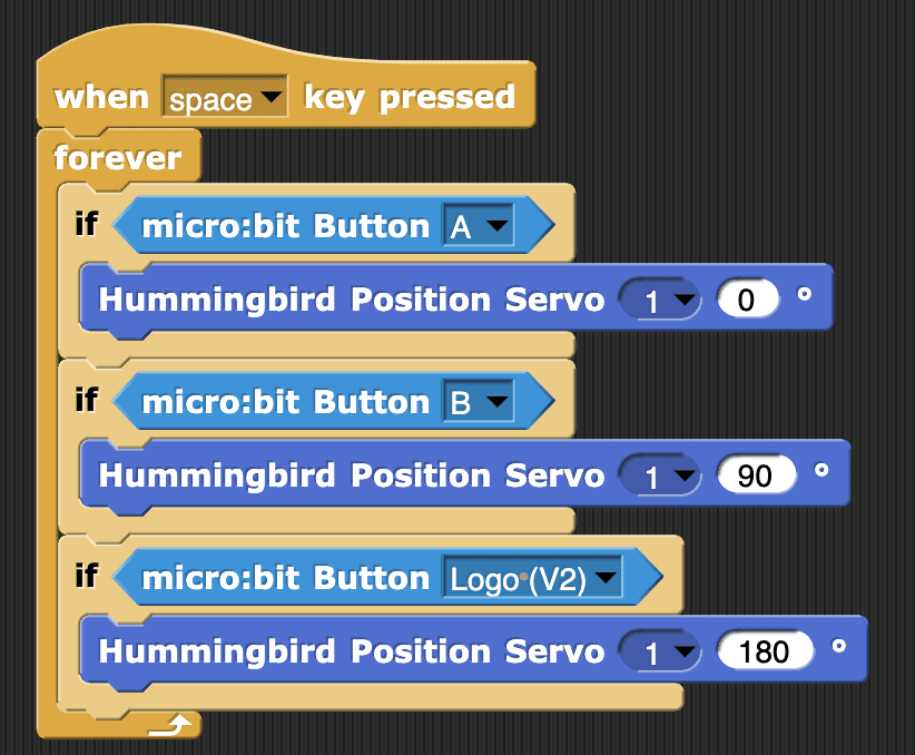
((img class=img-responsive src=https://learn.birdbraintechnologies.com/wp-content/uploads/2020/10/bitsnap2-768x374.png))CHALLENGE
Write a program that moves the position servo to 0° when you press button A, 90° when you press button B, and 180° when you touch the logo.
Click Here to see example code.
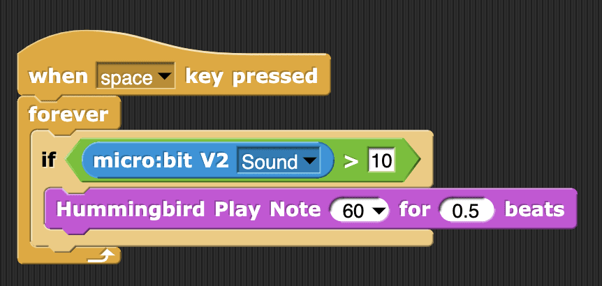
The Sound Sensor
The micro:bit sound sensor can detect a noise like a clap. This is similar to the sound sensor that comes with the Hummingbird Premium kit, but it is contained in the micro:bit rather than a separate sensor. The range of the sound sensor is 0-100.
The sound sensor is the default option in the micro:bit Sound/Temperature block. For example, you can make the rotation servo stop when the Hummingbird detects a noise.
((img class=img-responsive src=https://learn.birdbraintechnologies.com/wp-content/uploads/2020/10/bitsnap4-768x511.png))If you do not have a micro:bit V2, the micro:bit V2 Sound/Temperature block will report “micro:bit V2 required” when you try to use it.
((img class=img-responsive src=https://learn.birdbraintechnologies.com/wp-content/uploads/2020/10/bitsnap5.png))CHALLENGE
Make the Hummingbird play a note when you clap your hands.
Click Here to see example code.
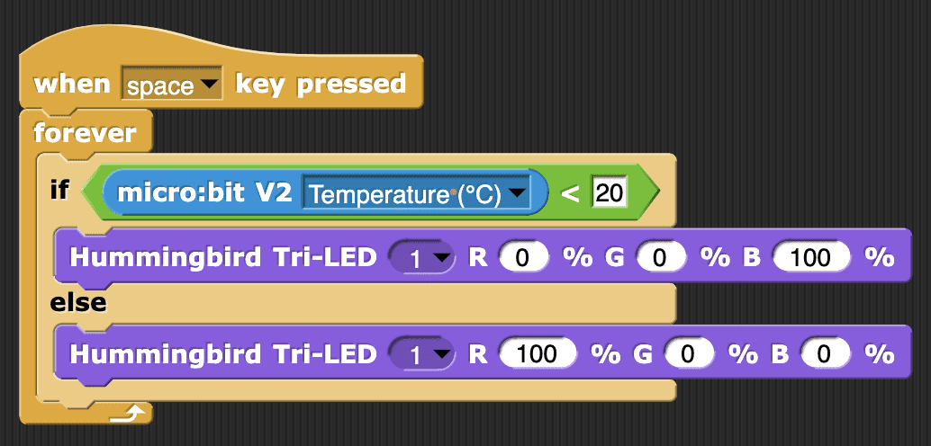
The Temperature Sensor
The micro:bit temperature sensor returns the temperature in degrees Celsius. This sensor is a drop-down option in the micro:bit Sound/Temperature block. For example, you can display an “H” on the micro:bit when the temperature is warmer than 20 degrees, and a “C” otherwise.
((img class=img-responsive src=https://learn.birdbraintechnologies.com/wp-content/uploads/2020/10/bitsnap7-768x466.png))CHALLENGE
Make a tri-color LED turn blue when the Hummingbird detects that it is cold and red otherwise.
Click Here to see example code.
Rover: Video Control
What is a variable? In programming, a variable is a value that can change, depending on conditions or on information passed to the program. Using variables with the Hummingbird Robotics Kit will help you create robots with more advanced functions.
Before you begin this module, make sure that you have completed the single color LED module, the position servo module, the buttons module, and at least one of the sensor modules.
You can name a variable anything you want, but it makes most sense to give it a name that matches its function. In this module, we are creating a variable that counts up and down when the A and B buttons are pressed, so a good name for this variable is “count.”
Nesting a variable into an output block is one way to use a variable. You can also use a variable to control robot expressions. If the variable equals 1, your robot can perform one set of actions. If you variable equals 2, your robot can perform a different set of actions.
Try building a robot using the variable to control different expressions. You can build any type of robot you want, but we recommend building the Tiny Drummer.
Creating a variable that counts on its own will require a good understanding of how loops work and of how wait blocks work. Create a variable that counts upwards on its own, then associate that counting variable with an LED. How does the LED react?
Programming a position servo to move slowly is very similar to programming an LED to fade in and out. Nest the counting variable block inside of a position servo block instead of an LED block.
To manually control the speed of that position servo with the A and B buttons we will need a new variable. Create a second variable and call it “time.”
If the wait time between servo positions is too big or too small, the servo can become difficult to work with. Set some parameters for your time variable. There are many ways to set variable parameters.
Try to build a robot that uses 2 slow moving servos. You can build anything you want, but we recommend the Little Bot.
Rover: Compass
In this module, you will program a mobile robot to move and avoid obstacles. You will need a rover for this module, so go ahead and build one with this tutorial. We kept our rover pretty simple, but feel free to make yours a parade float, a bananamobile, or whatever you can dream up!
Note: The rover modules assume that you have already completed the modules in the Inputs and Outputs sections.
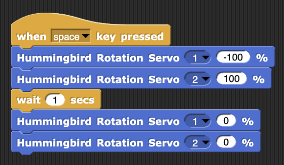
Moving Forward and Back
The two rotation servos on the rover point in opposite directions.
This means that to move the rover forward, the two servos must move in opposite directions.
((img class=img-responsive src=https://learn.birdbraintechnologies.com/wp-content/uploads/2020/10/image4.png))To move the rover forward, set the speed of rotation servo 1 to 100% and the speed of rotation servo 2 to -100%.
((img class=img-responsive src=https://learn.birdbraintechnologies.com/wp-content/uploads/2020/10/image8-2.png))CHALLENGE
Try out this code. Experiment with different wheel speeds to see how you can move the rover in different ways. How can you move backward?
Click Here to see example code.
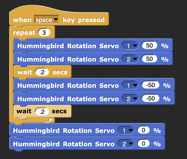
Turning
When the speeds of the rotation servos are equal, the robot turns in place.
Notice that this code turns the rotation servos off at the end of the program. Otherwise, they will remain on when the script ends, and the rover will keep spinning.
((img class=img-responsive src=https://learn.birdbraintechnologies.com/wp-content/uploads/2020/10/image20-2.png))CHALLENGE
Try out this code. How can you change how far the robot turns?
Click Here to see example code.
Avoiding Obstacles
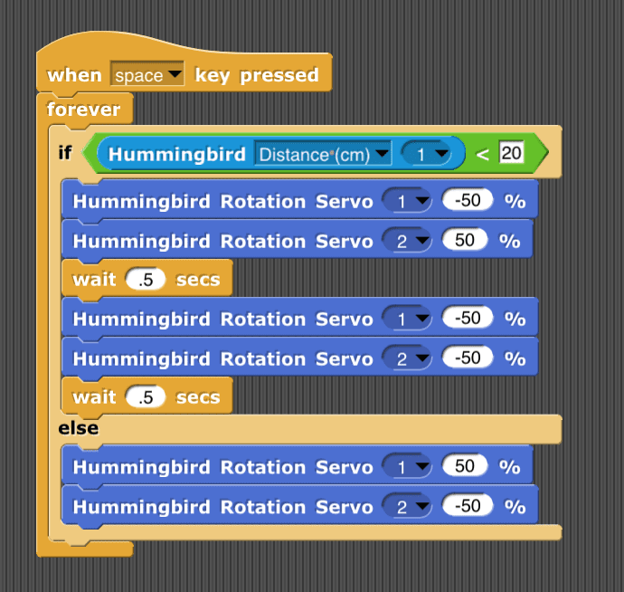
You can use the distance sensor to help your robot avoid obstacles. This program will stop the rover when it sees an obstacle less than 20 cm away. Otherwise, the rover will move forward.
((img class=img-responsive src=https://learn.birdbraintechnologies.com/wp-content/uploads/2020/10/image27-2.png))CHALLENGE
Modify your program to make the rover back up and turn left when it sees an obstacle. Now your rover can wander around the room!
Click Here to see example code.
Adding Extras
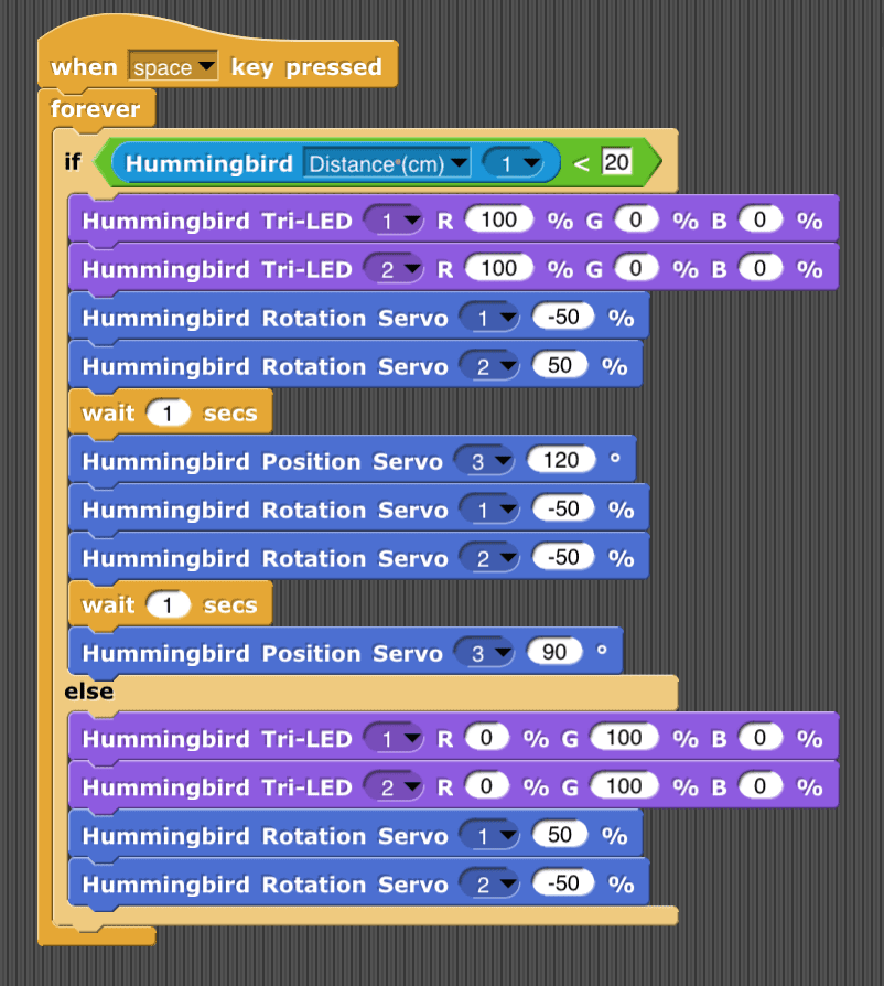
The rover also has two tri-color LEDs for headlights and a servo that controls the steering wheel. You can incorporate these components into your program as well.
CHALLENGE
Make the headlights turn red when the rover is moving away from an obstacle and green when the rover is moving forward. Make your driver steer by turning the steering wheel to the left as the robot turns left and back to the center when it is moving forward or back.
Click Here to see example code.
Rover: Line Tracking
In this module, you will learn to generate random numbers and use them to create interesting and sometimes unexpected behaviors for your rover. For example, you can use random numbers to make the rover move randomly with random colors for the headlights.
Generating Random Numbers
The pick random block is on the Operators menu in Snap!. This block randomly chooses a number between the two limits given. For example, this block generates a number between 1 and 100. Each time you click the block, it will give you a different number.
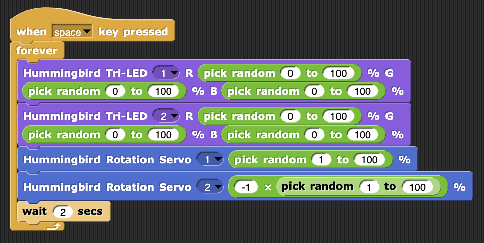
((img class=img-responsive src=https://learn.birdbraintechnologies.com/wp-content/uploads/2020/10/image31-1.png))You can use the pick random block anywhere that you would use a number in your program. For example, this program sets the speed of each rover wheel to a random number every two seconds. This program will make your rover wander randomly about the room!
Notice that each wheel gets a different random number, so the Finch will mostly turn but sometimes move straight. The random number for rotation servo 2 is multiplied by -1 to make this number negative.
((img class=img-responsive src=https://learn.birdbraintechnologies.com/wp-content/uploads/2020/10/image11-2-768x244.png))CHALLENGE
Use the pick random block to set the rover headlights to different random colors as the Finch moves randomly around the room.
Click Here to see example code.
Randomness with Variables
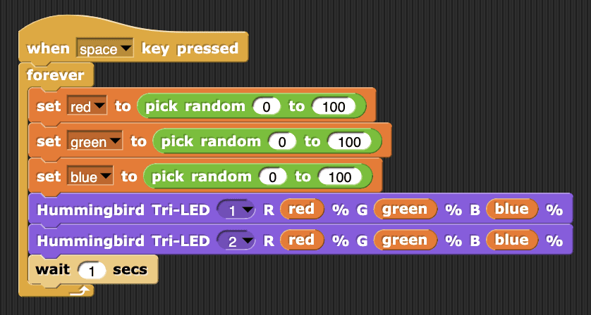
If you want to set both headlights to the same random color, you can add a variable to your program. Create a variable called red. If you need more information about how to make and use a variable, refer to the Variables module.
Set your variable equal to a random number between 0 and 100. Then set the amount of red for the tri-color LEDs to red.
((img class=img-responsive src=https://learn.birdbraintechnologies.com/wp-content/uploads/2020/10/image26-2.png))CHALLENGE
Create two variables, green and blue. Set each of these variables to a random number, and then use these variables to set the amount of green and blue light for both tri-color LEDs. When you are done, your program should set both tri-color LEDs to the same random color every second.
Click Here to see example code.
Flower: Sensor Control
Snap! contains blocks that use your computer’s camera. This module will show you how to use these blocks to write a program to control the rover by moving in front of your camera.
Note: This module requires that your computer have a camera.
Measuring Video Motion
The video block on the Sensing menu accesses the computer’s camera. Click on this block and give Snap! permission to use your camera. You will notice that the background of the stage changes to show your camera view.
((img class=img-responsive src=https://learn.birdbraintechnologies.com/wp-content/uploads/2020/10/image28-2.png))The video block has two drop-down menus. In the second drop-down, you can select the sprite or the stage. This determines whether Snap! will measure the video at the location of the sprite or across the entire stage. Select Stage so that you can measure the motion anywhere in the camera view. The first drop-down is set to motion by default. This means that the block will measure a positive value that tells you how much objects in the video are moving. For example, this code will show the amount of motion measured; the wait block is included so that the numbers change slowly enough to be readable.
((img class=img-responsive src=https://learn.birdbraintechnologies.com/wp-content/uploads/2020/10/image18-2.png))CHALLENGE
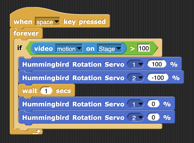
Write a program that moves the rover forward for one second when the amount of video motion on the stage is greater than 100.
Click Here to see example code.
Measuring the Direction of Motion
You can measure the direction an object is moving on the camera by selecting direction in the first drop-down on the video block. The direction value is between -180° and 180°, where 0° points towards the top of the screen. For example, this code will make the sprite on the screen point in the direction of the video motion. The point in direction block is on the Motion menu.
((img class=img-responsive src=https://learn.birdbraintechnologies.com/wp-content/uploads/2020/10/image6-2-768x263.png))If you need to consider both the motion and its direction, you can use one decision statement nested inside another. For example, if the motion is greater than 100, then this code will test whether the direction is greater than 0. If it is, the tri-color LED turns green. If the motion is less than or equal to 100, the tri-color LED turns red.
((img class=img-responsive src=https://learn.birdbraintechnologies.com/wp-content/uploads/2020/10/image32-1-768x463.png))CHALLENGE
Write a program to make the rover move forward when the direction is greater than 0° and backward otherwise. The rover should only move if the motion is greater than 100.
Click Here to see example code.
Using Video with Sprites
The video motion block can also measure movement and the direction of movement of a sprite in the video scene. For example, Sprite is selected in the video block in this code. When you run this code, the rover will only move when the video shows you moving over the sprite. Moving in other parts of the stage will not make the rover move. Notice that here the motion threshold is only 50. This is because all of the motion measurements will be smaller because you are only measuring motion over the sprite.
((img class=img-responsive src=https://learn.birdbraintechnologies.com/wp-content/uploads/2020/10/image4-2.png))Add a new sprite in Snap! by pressing the new sprite button in the lower right of the screen. Then you will see that you have two sprites.
((img class=img-responsive src=https://learn.birdbraintechnologies.com/wp-content/uploads/2020/10/image23-2-768x438.png))Each sprite has its own scripts, so when you create the second sprite, the Scripts area on the screen is blank. This is where you can write scripts for the second sprite. The scripts you already wrote for the first sprite are still there, but you have to select the first sprite in the lower right corner in order to see them.
((img class=img-responsive src=https://learn.birdbraintechnologies.com/wp-content/uploads/2020/10/image1-2-768x357.png))Now you can write scripts that use the motion across both sprites. For example, this code will move the rover forward when you move across the first sprite and backward when you move across the second one.
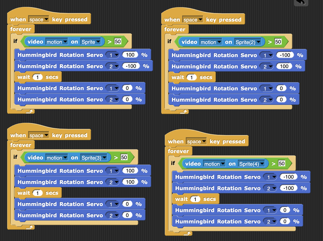
((img class=img-responsive src=https://learn.birdbraintechnologies.com/wp-content/uploads/2020/10/image22-2-768x299.png))CHALLENGE
Add two more sprites. Write scripts so that you can use the video motion across the four sprites to make the rover move forward, move backward, turn left, and turn right.
Click Here to see example code.
Flower: Control with Variables
In this module, you will learn to use the compass that is on the micro:bit to make your robot move in a particular direction.
The compass tells you the direction of your micro:bit relative to magnetic north. You can make your rover drive north while avoiding obstacles!
Calibrating the Compass
Before you use the compass, you need to calibrate it in the BlueBird Connector.
To do this, connect to your Hummingbird Bit and click on the purple compass button next to the name of your device. Follow along with the video to move your Bit around in different directions to calibrate it. You should see a green check when you have successfully calibrated. If you see a red X, try again.
((img class=img-responsive src=https://learn.birdbraintechnologies.com/wp-content/uploads/2020/10/image10-2-768x417.png))The micro:bit Compass Block
Once you have successfully calibrated, you can use the micro:bit Compass block on the Sensing menu to read the value of the compass.
((img class=img-responsive src=https://learn.birdbraintechnologies.com/wp-content/uploads/2020/10/image2-2.png))The compass value will be between 0° and 359°. 0° corresponds to the direction of magnetic north. The angle increases as the robot turns clockwise, so 90° is east, 180° is south, and 270° is west.
To use the compass, the micro:bit must be positioned so that the LED display is parallel to the ground. Otherwise, the compass will not provide useful measurements.
((img class=img-responsive src=https://learn.birdbraintechnologies.com/wp-content/uploads/2020/10/image14-768x649.png))CHALLENGE
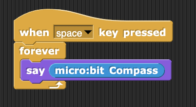
Write a program that continually displays the value of the compass on the computer screen. Watch this value change as you slowly turn the rover.
Click Here to see example code.
Displaying Direction
You can use the compass to make the rover tell you the direction it is heading in.
For example, if the value of the compass is between 45 and 135, use the say block to print “East” on the screen
You can use the and block on Operators menu to combine comparisons. The and block will be true only when both Boolean blocks inside it are true.
((img class=img-responsive src=https://learn.birdbraintechnologies.com/wp-content/uploads/2020/10/image33-768x302.png))CHALLENGE
Add a second if else block to your script as shown. Modify the nested if else to show “South” when the value of the compass is between 135 and 225.
Click Here to see example code.
((img class=img-responsive src=https://learn.birdbraintechnologies.com/wp-content/uploads/2020/10/image3-2-768x389.png))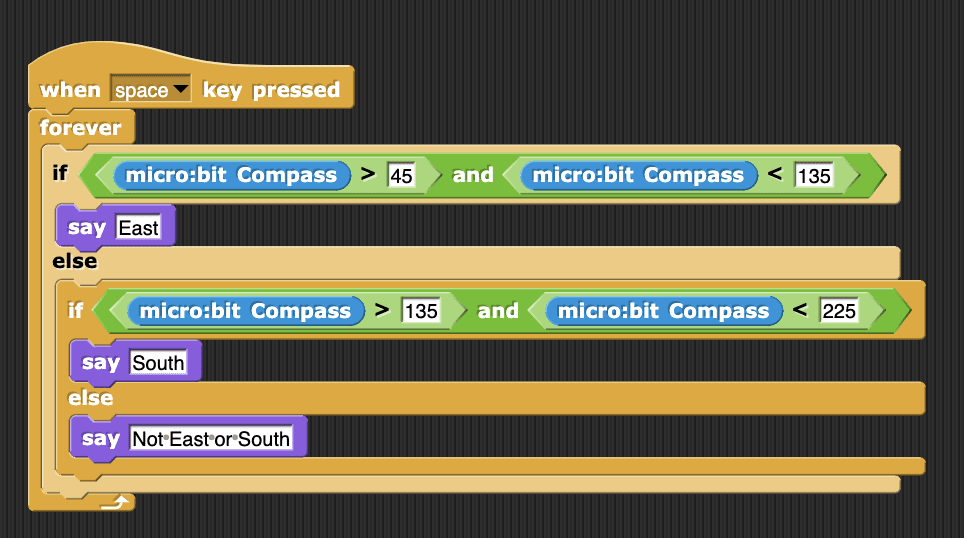
Driving with the Compass
You can also use the compass to make the rover move in a particular direction. For example, this code makes the robot turn clockwise when the compass is less than 180° and counterclockwise otherwise. Try placing the rover in different positions before running this script. Which direction does the rover drive in?
((img class=img-responsive src=https://learn.birdbraintechnologies.com/wp-content/uploads/2020/10/image30-1.png))CHALLENGE
Modify your program so that the robot drives south as long as there is no obstacle in the way. When the robot encounters an obstacle, it should back up and turn.
Click Here to see example code.
Making a Line Tracking Sensor
You will use a single color LED and a light sensor to create a line tracking sensor. To track a black line on a light-colored surface, you need to know whether the sensor is over a black surface or a white surface. You can determine this by measuring the amount of light reflected by the surface. A white (or light-colored) surface reflects a lot of light, while a black surface reflects very little light.
((img class=img-responsive src=https://learn.birdbraintechnologies.com/wp-content/uploads/2020/10/linetracking-schematic-768x475.png))In addition to a single color LED and a light sensor, you will need a piece of cardboard that is roughly 8 cm by 15 cm and a metal brad.
((img class=img-responsive src=https://learn.birdbraintechnologies.com/wp-content/uploads/2020/10/build1-768x564.png))Poke holes in the cardboard so that you can mount the LED and the light sensor close together along one of the long edges of the cardboard. Use the metal brad to hold the light sensor in place.
((img class=img-responsive src=https://learn.birdbraintechnologies.com/wp-content/uploads/2020/10/build2-768x534.png))Glue the piece of cardboard to the bottom of the rover’s rotation servos, the LED and the light sensor should be pointing at the ground and 1-2 cm away from the ground.
Connect the single color LED to LED port 1 and the light sensor to sensor port 2.
((img class=img-responsive src=https://learn.birdbraintechnologies.com/wp-content/uploads/2020/10/build3-768x283.png))Making a Line to Track
To create a line to track, you will need large sheets of white paper and black electrical tape about 2 cm wide. Use the tape to make a black line on a white background. Avoid sharp turns; it is easier for the rover to follow gradual curves.
((img class=img-responsive src=https://learn.birdbraintechnologies.com/wp-content/uploads/2019/12/image1-7-1.png))Basic Line Tracking
To track a line, the rover should turn right or left based on whether or not it detects the line. Let’s think about tracking the left side of the line as the rover moves clockwise around the loop. When the line sensor is over the black line, the rover should turn left. When the line sensor is over the white line, the rover should turn right.
Notice that this sample code uses the rotation servos to turn using only one wheel at a time. This means that both turns move the robot slightly forward. As the program repeats the if else block over and over, the rover will follow the line as it turns back and forth.
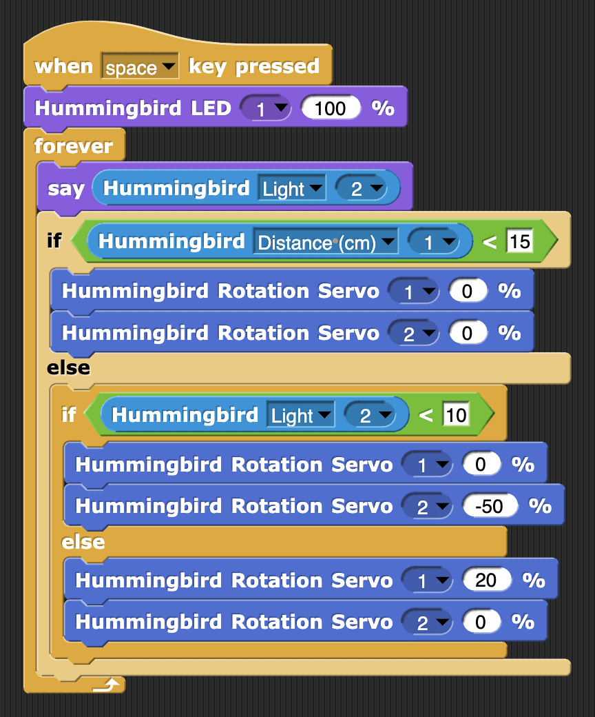
Note 1: As you run a Snap! program, the app relays commands over Bluetooth to the robot. There is some delay in this process, and that means that you need to turn slowly to track the line.
Note 2: Rotation servos can vary a lot, so what is a slow speed for one motor may not be for another motor. For example, in the sample code one motor is running at 20% while the other runs at -50%.
((img class=img-responsive src=https://learn.birdbraintechnologies.com/wp-content/uploads/2020/10/snaplinetrack1-768x670.png))CHALLENGE
Try out this code. You may need to adjust the line sensor threshold and the turning speed of each rotation servo in order to track your line. The say block will show you the light sensor value so that you can choose a good threshold.
More Line Tracking
You can combine line tracking with other robot behaviors to make more complex programs! For example, the robot can track the line only until it finds an obstacle or hears a loud noise.
CHALLENGE
Write a program that makes the rover track a line but stops the rover when there is an obstacle in front of it.
Click Here to see example code.
In this module, you will write Snap! programs to control a robotic flower. You will need a flower for this module, so use these instructions to build one if you haven’t already.
You should also connect a dial sensor to sensor port 1 for this module.
Note: The flower modules assume that you have already completed the modules in the Inputs and Outputs sections.
The Dial Sensor
You will start by using the Bit dial sensor to control the LEDs.
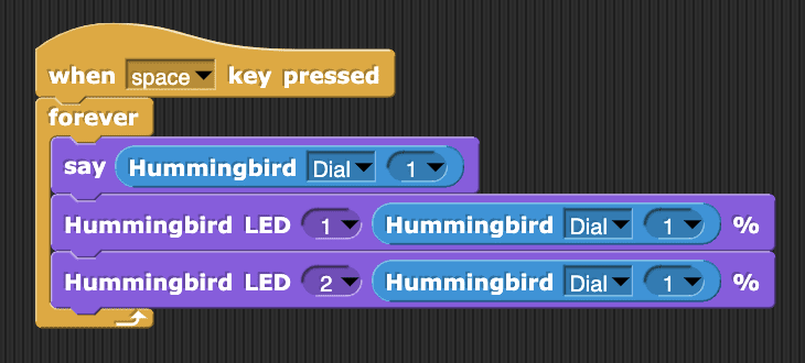
A convenient way to see the value of the sensor is to use the say block on the Looks menu. Use a forever loop to continually display the value of the sensor on the screen.
((img class=img-responsive src=https://learn.birdbraintechnologies.com/wp-content/uploads/2020/10/image17-4.png))CHALLENGE
Use the dial to control the brightness of the single color LEDs.
Click Here to see example code.
Math Blocks with the Dial
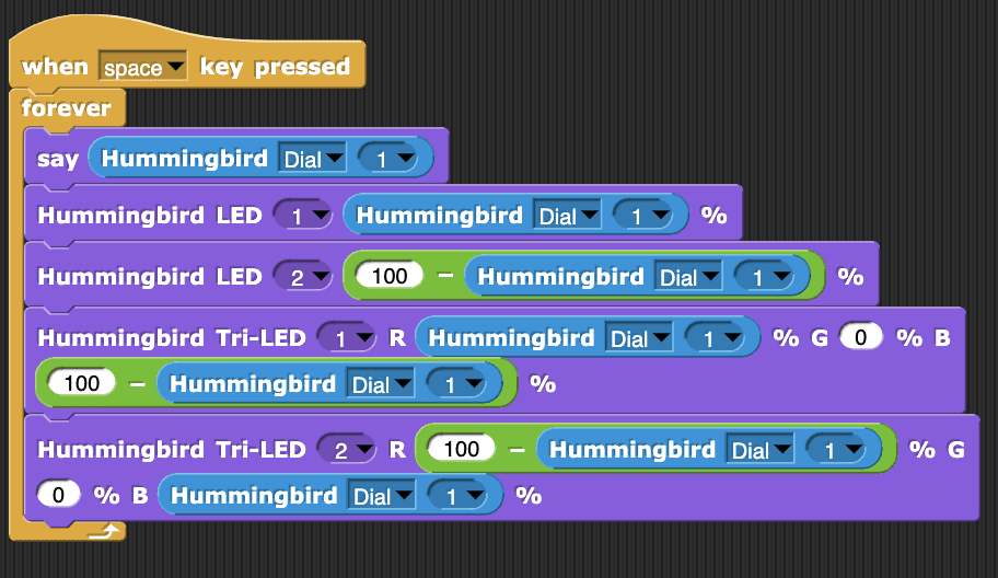
You can also use the math blocks on the Operators menu to change the behavior of your program. For example, this program will also make tri-color LED 1 gradually change from blue to red as you turn the dial from 0 to 100.
((img class=img-responsive src=https://learn.birdbraintechnologies.com/wp-content/uploads/2020/10/image10-5-768x353.png))CHALLENGE
Modify your project as follows:
- LED 2 should go from fully on to fully off as you turn the dial from 0 to 100.
- Tri-color LED 2 should change from red to blue as you turn the dial from 0 to 100.
Click Here to see example code.
The Accelerometer
You can also use the accelerometer to control how much the flower blooms.
The micro:bit accelerometer measures how much the micro:bit is tilting in three different directions, which are called x, y, and z. The value of the acceleration is between -10 m/s2 and 10 m/s2 for each direction.
((img class=img-responsive src=https://learn.birdbraintechnologies.com/wp-content/uploads/2020/10/image1-4.png))You can measure the acceleration in the x, y, and z directions using the micro:bit Accelerometer block on the Sensing menu.
((img class=img-responsive src=https://learn.birdbraintechnologies.com/wp-content/uploads/2020/10/image15-4.png))CHALLENGE
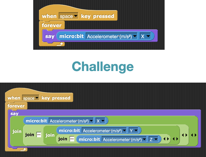
Write a program to see the x-value of the accelerometer change as you tilt the Hummingbird in different directions. For an extra challenge, display the y– and z-values of the accelerometer as well (Hint: The join block on the Operators menu may be helpful).
Click Here to see example code.
Math Blocks with the Accelerometer
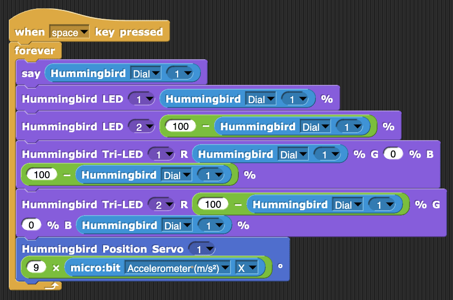
The x-value of the acceleration is between -10 and 10. To make the flower bloom, we want to use this value to calculate an angle for the position servo.
For example, if we calculate the angle by multiplying the x-acceleration by 4 then as the x-value of the acceleration changes from 0 to 10, the angle will change from 0° to 40°.
((img class=img-responsive src=https://learn.birdbraintechnologies.com/wp-content/uploads/2020/10/image4-4-768x501.png))CHALLENGE
Adjust the program so that the flower fully blooms as you tilt the Hummingbird Bit to the left (so that the sensor ports are toward the table and the LED ports point toward the ceiling).
Click Here to see example code.
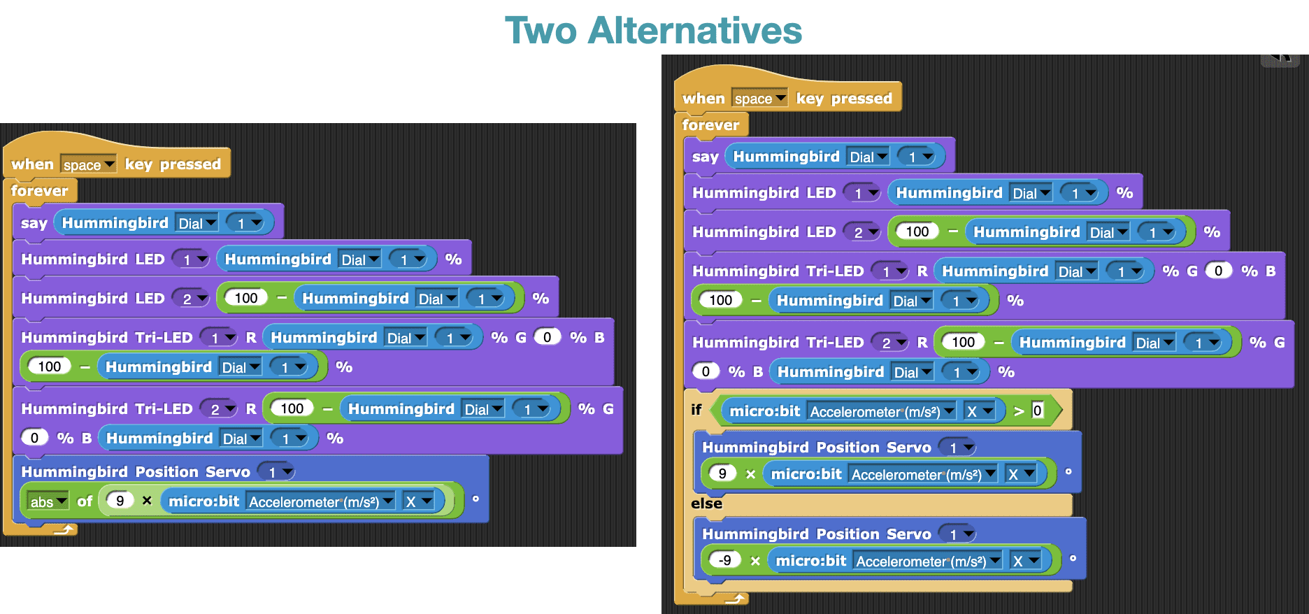
CHALLENGE
The flower doesn’t bloom when you tilt the Bit to the right because the micro:bit x-acceleration is less than 0. How can you make your flower bloom when you tilt the Bit to the right or left?
Hint: You can do this using an if else block or a block from the Operators menu.
Click Here to see example code.
The repeat Block
You have been using forever loops to repeat blocks. You can also use the repeat block on the Control menu.
This block repeats whatever is inside it a certain number of times.
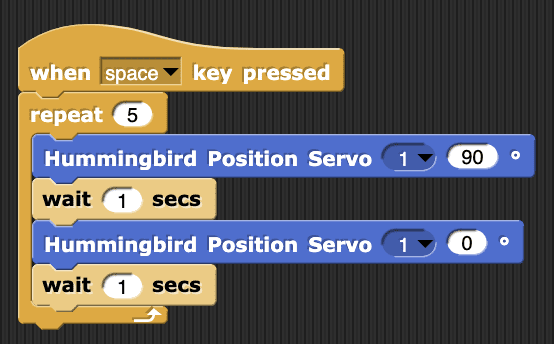
For example, this code will make an LED turn on and off 10 times.
((img class=img-responsive src=https://learn.birdbraintechnologies.com/wp-content/uploads/2020/10/image18-4.png))CHALLENGE
Write a program to make the flower open and close 5 times.
Click Here to see example code.
Loops with Variables
To make the flower bloom gradually, you will use the repeat block with a variable. A variable is a name that represents a value. You can use it to store information.
Go to the Variables menu and click Make a variable. Name your variable count.
((img class=img-responsive src=https://learn.birdbraintechnologies.com/wp-content/uploads/2020/10/image19-4.png))You will notice that the Variables menu looks different now. It contains a block for your variable and blocks to change its value.
((img class=img-responsive src=https://learn.birdbraintechnologies.com/wp-content/uploads/2020/10/image11-4.png))CHALLENGE
Try out this code and watch the value of count. What does the change by block do? How does the value of count at the end of the script depend on the number in the repeat block?
((img class=img-responsive src=https://learn.birdbraintechnologies.com/wp-content/uploads/2020/10/image8-5.png))Loops with Variables
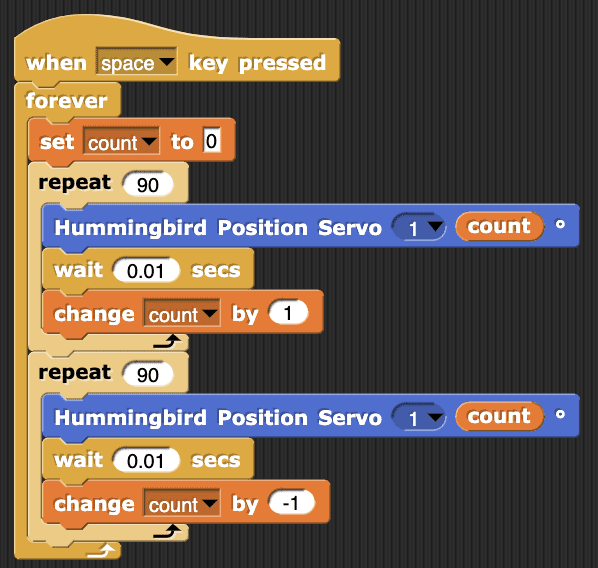
Make your flower bloom gradually using the repeat block and count. Set the number in the repeat block to be the “full bloom” angle for your flower (yours may be different than 90°). Each time through the loop, set the position servo to count and stop briefly. You can vary the length of the wait to make your flower bloom more slowly.
((img class=img-responsive src=https://learn.birdbraintechnologies.com/wp-content/uploads/2020/10/image23-3.png))To make the flower bloom repeatedly, place the code inside a forever loop.
((img class=img-responsive src=https://learn.birdbraintechnologies.com/wp-content/uploads/2020/10/image7-5.png))CHALLENGE
With one repeat block, the flower blooms gradually and then closes quickly. To make the flower close gradually as well, add a second repeat block. Make the angle of the servo go from 90° to 0° by changing count by -1.
Click Here to see example code.
Adding Loops
You can also use a variable to change the color of the tri-color LEDs.
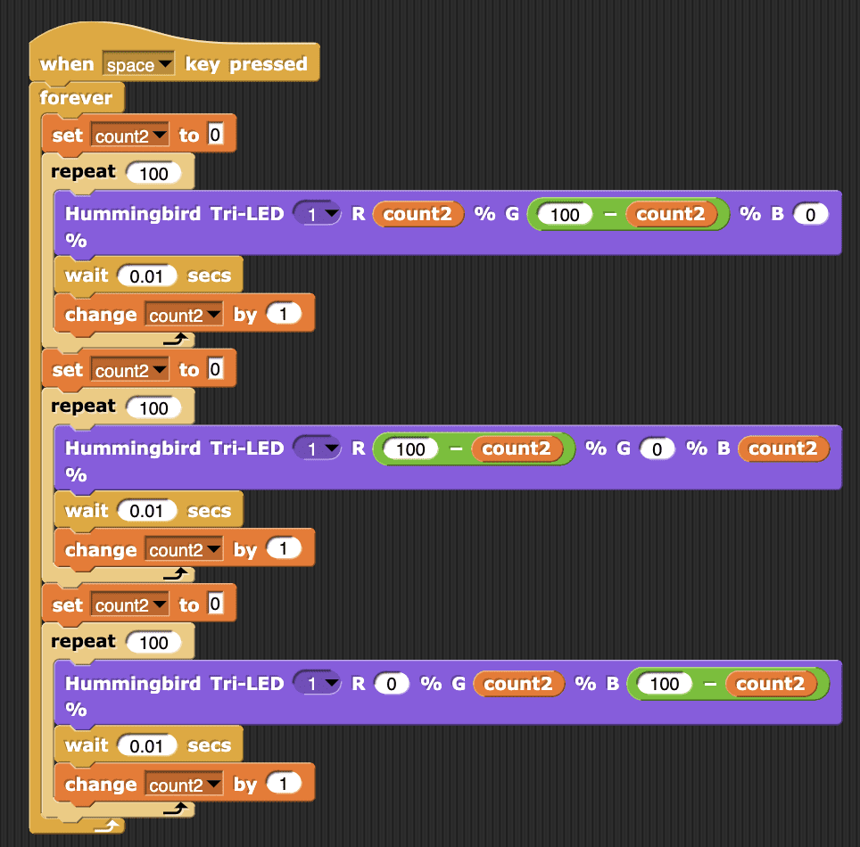
Add a second variable and a second forever loop with a repeat inside. To make the LED change from green to red, use a subtraction block to make green decrease from 100 to 0 as red increases from 0 to 100.
((img class=img-responsive src=https://learn.birdbraintechnologies.com/wp-content/uploads/2020/10/image2-5-768x341.png))CHALLENGE
Add two more repeat blocks to your tri-color LED script. Make the LED change from green to red, then red to blue, then blue back to green. Make the program repeat this sequence until you press the stop button.
Click Here to see example code.
CHALLENGE
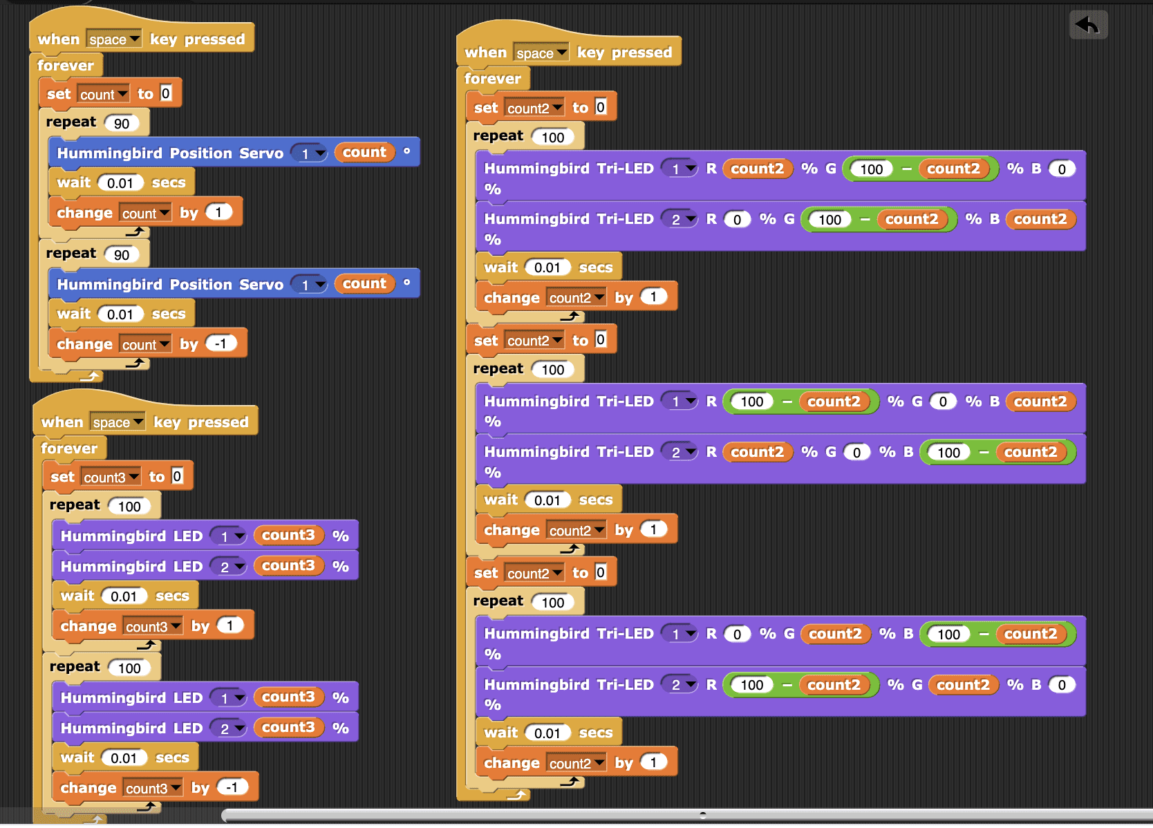
Add tri-color LED 2 and the single color LEDs to your code. Make tri-color LED 2 gradually change color in a different sequence from tri-color LED 1.
Click Here to see example code.
For Loops
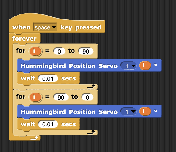
Snap! also contains a loop called a for loop. The for block on the Control menu is a loop that creates a variable called i. The variable i automatically changes from the first value specified in the for block to the second. Each time through the loop, the value of i automatically changes by one. This means that this program also gradually changes tri-color LED 1 from green to red! In this lesson, we focused on declaring our own variables, but you can explore how to use for blocks in your Hummingbird programs.
((img class=img-responsive src=https://learn.birdbraintechnologies.com/wp-content/uploads/2020/10/image20-4-768x240.png))CHALLENGE
Make the flower gradually bloom and close using for loops.
Click Here to see example code.
Learn more about artificial intelligence with hands-on Hummingbird activities. This video shows an example of the fun activities you can do! The program uses image recognition to distinguish candy from a drawing of brains to make a Zombie Hummingbird respond appropriately.